Microencapsulation seal for coaxial cable connectors and method of use thereof

a technology of microencapsulation and coaxial cable, which is applied in the direction of electrically conductive adhesive connections, coupling device connections, electrical apparatus, etc., can solve the problems of inability to control, additional problems within the connector, and lower performance and eventual need to replace the connector

Inactive Publication Date: 2010-11-09
PPC BROADBAND INC
View PDF11 Cites 35 Cited by
  • Summary
  • Abstract
  • Description
  • Claims
  • Application Information

AI Technical Summary

Problems solved by technology

The introduction of water and / or water vapor to the inside of a coaxial cable connector can cause destruction of the inside of the coaxial cable connector resulting in lower performance and the eventual need to replace the connector.
Similarly, other corrosive vapors can cause destruction by entering the coaxial cable connector through tiny holes between the inner and outer portions of the connector as well as between the connector and the coaxial cable.
These injection methods have been successful in preventing moisture damage, however they have also created additional problems within the connectors.
One such problem is the inability to control where the injected material goes once inside the connector, thereby damaging other components of the connector.
In addition the injected material could seep out of other holes in the connectors and create problems for the installer.
The injection method also makes installation more difficult because it requires the installer to use additional materials and tools to perform the installation.
Difficult installation is unfavorable because coaxial cable connectors are often installed in towers located high off the ground.
This method could still result in moisture coming into contact with the pin and destroying the connector if there were any deformities in the elastomeric layers.
Even the slightest crack or hole would be enough to enable water to enter the connector and cause damage.
In addition, this method requires additional components to be manufactured as well as an additional step in the assembly process, resulting in a more expensive connector.
This requires the installer to carry extra materials and tools with him / her and makes the installation process more difficult.

Method used


Image

  • Microencapsulation seal for coaxial cable connectors and method of use thereof
  • Microencapsulation seal for coaxial cable connectors and method of use thereof
  • Microencapsulation seal for coaxial cable connectors and method of use thereof

Examples


first embodiment

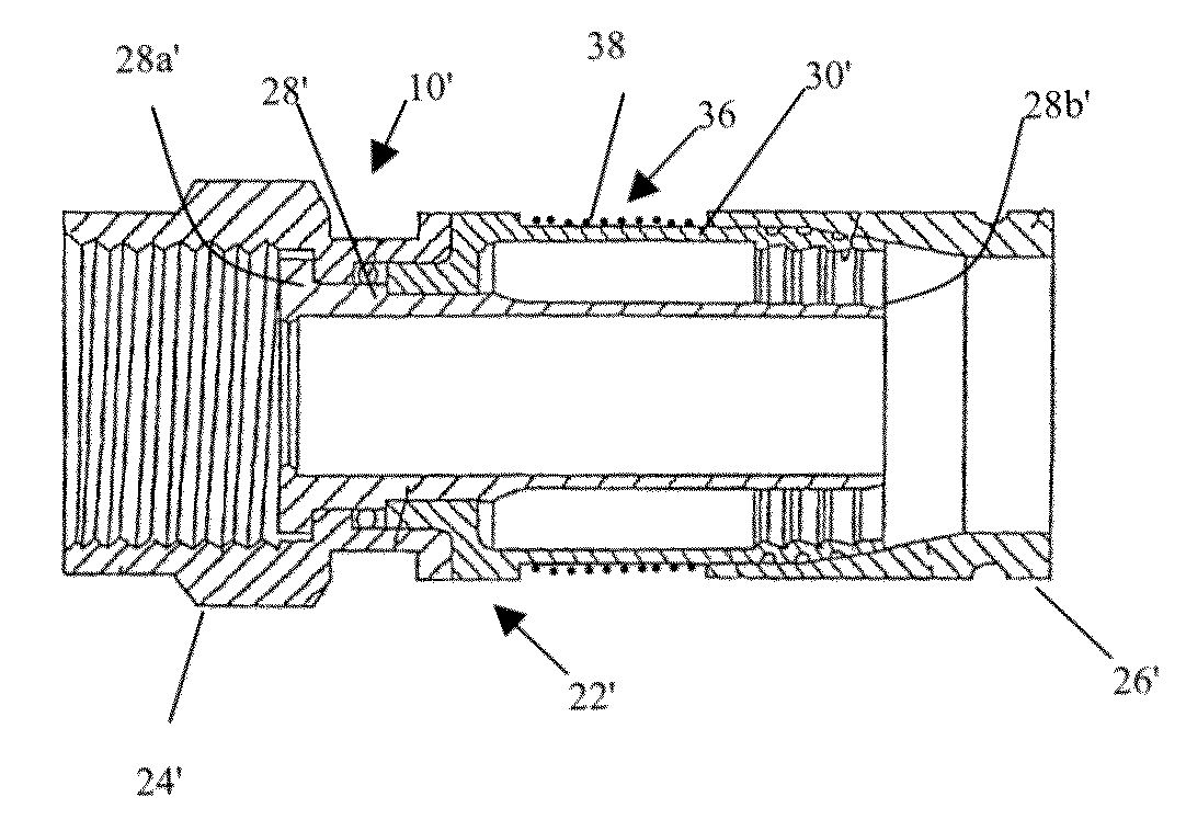
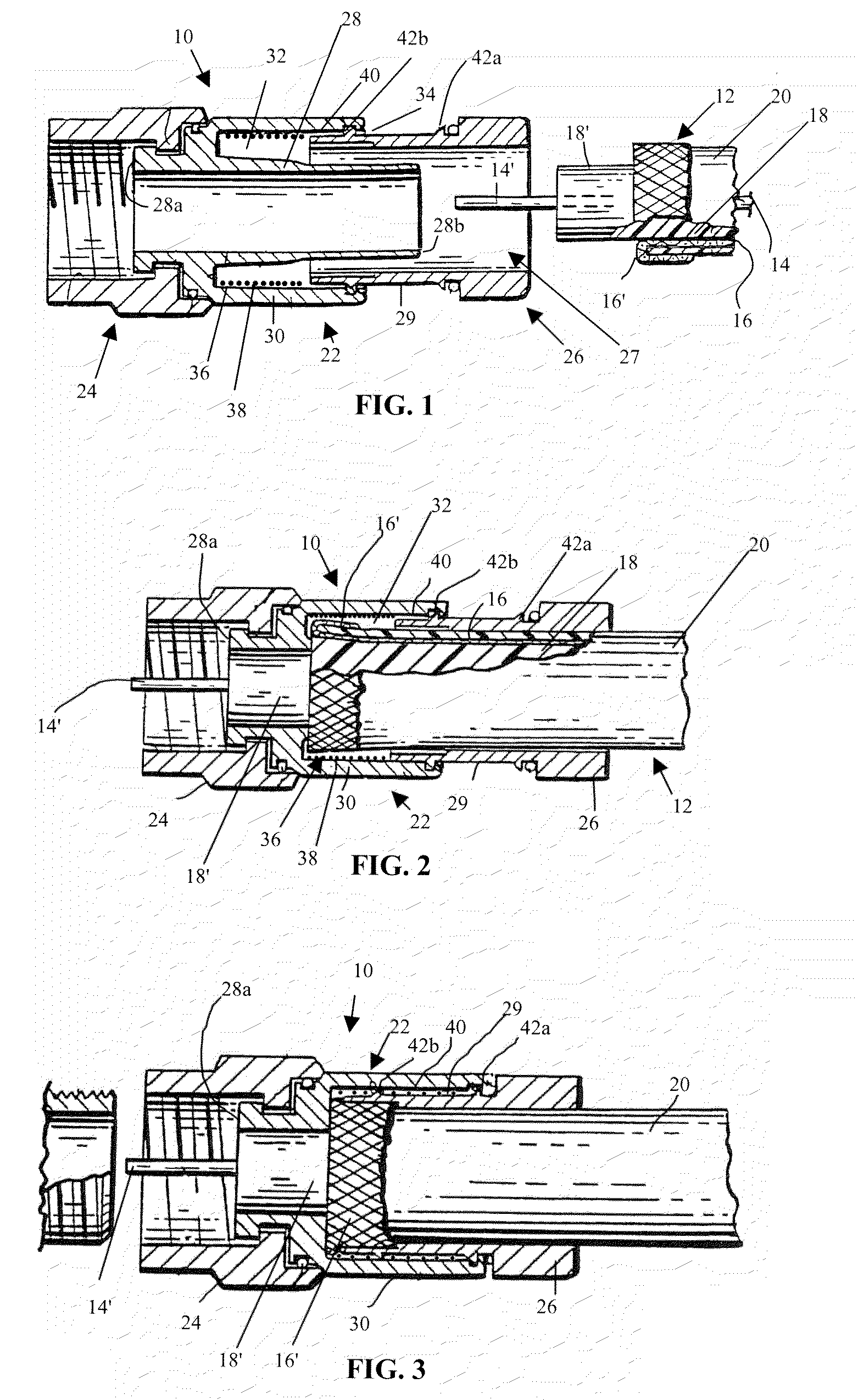
[0033]Coaxial cable connector 10 includes a connector body 22, a cylindrical fastener 24 and a compression member 26. Connector body 22 comprises a tubular inner post 28 extending from a front end 28a to a rear end 28b, and an outer cylindrical collar 30 surrounding and fixed relative to the inner post 28 at a location disposed rearwardly of the front end 28. Outer cylindrical collar 30 cooperates in a radially spaced relationship with the inner post 28 to define an annular chamber 32 accessible via a rear opening 34. In a first embodiment, an adhesive layer 36, located on an inner surface 40 of outer cylindrical collar 30, includes microcapsules 38 (shown in stipple) of an adhesive material. Adhesive layer 36 extends around the circumference of inner surface 40 of outer cylindrical collar 30 and along a length of inner surface 40 that can vary depending on the degree of mechanical bonding action desired once the compression member 26 is advanced into connector body 22, at which tim...

second embodiment

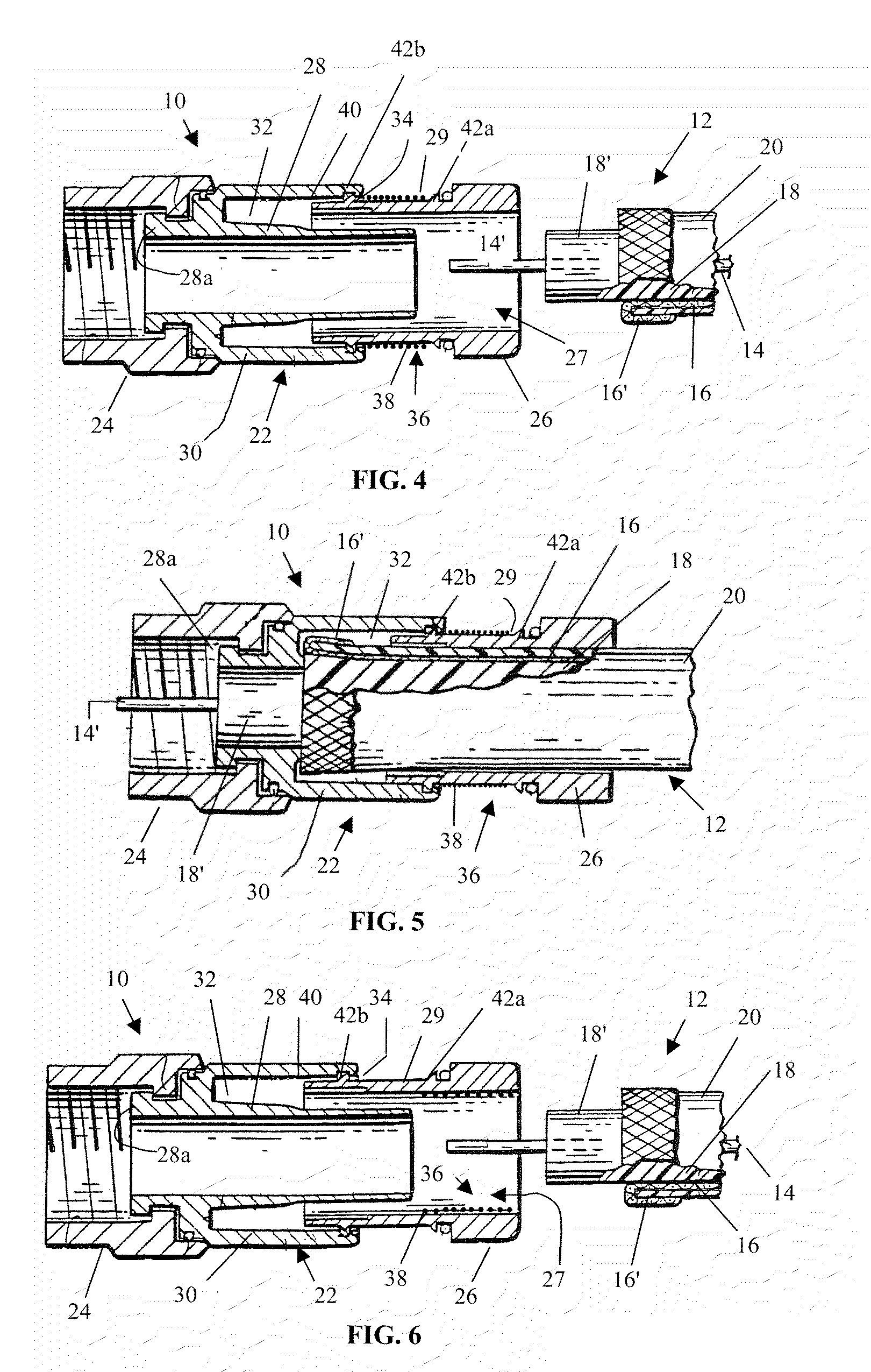
[0037]this invention can be seen in FIGS. 4 and 5. FIG. 4 shows an adhesive layer 36 of microcapsules 38 (in stipple) located on a portion of outer surface 29 of compression member 26. As shown in FIG. 5, when installing coaxial cable connector 10 on the prepared end of coaxial cable 12, the tubular inner post rear end 28b is first inserted axially into the cable end. Similar to FIG. 3, when the compression member 26 is compressed within connector body 22, the outer surface 29 of compression member 26 comes into contact with inner surface 40 of outer cylindrical collar 30 with sufficient pressure to rupture the microcapsules 38 of adhesive layer 36. The ruptured microcapsules 38 interact to form a bond between connector body 22 and compression member 26, thereby creating a mechanical connection and a moisture barrier.

third embodiment

[0038]FIGS. 6 and 7 show this invention. FIG. 6 shows the adhesive layer 36 of microcapsules 38 (shown in stipple) located on a portion of compression member internal passageway 27. As shown in FIG. 7, when installing coaxial cable connector 10 on the prepared end of coaxial cable 12, the tubular inner post rear end 28b is first inserted axially into the cable end. In this instance, a microcapsule configured to rupture at a lower applied pressure may be used so that as coaxial cable 12 is inserted into compression member internal passageway 27, microcapsules 38 of adhesive layer 36 are easily ruptured. Similar to FIG. 3, when the compression member 26 is compressed within connector body 22, the ruptured microcapsules 38 form a bond between compression member 26 and coaxial cable 12, thereby creating a mechanical connection and a moisture barrier.


PUM


Abstract

A coaxial cable connector comprising a connector body, a tubular inner post configured to receive a coaxial cable and a clamping member, whereby at least one surface of the coaxial cable connector is coated with microcapsules creating an adhesive material. An adhesive layer is pre-applied to defined components of the coaxial cable connector in their pre-assembled configuration to avoid increased labor for the connector installer and to ensure a minimal but uniform layer of the microencapsulated adhesive is present on the desired connector components. When the coaxial cable is inserted into and clamped within the coaxial cable connector, the microcapsules are ruptured by the resulting pressure. This results in an adhesive bond forming between the coaxial cable and the connector to create a secure, mechanical bond and moisture seal.

Description

CROSS-REFERENCE TO RELATED APPLICATIONS[0001]This application is a divisional application claiming priority from U.S. Utility pat. application Ser. No. 11 / 777,594 filed Jul. 13, 2007 now abandoned, the disclosure of which is herein incorporated by reference.FIELD OF THE INVENTION[0002]This invention relates generally to coaxial cable connectors. More particularly, the present invention relates to a microencapsulation seal for coaxial cable connectors and a related method of use.BACKGROUND OF THE INVENTION[0003]Conventional coaxial cable typically consists of a centrally located inner electrical conductor surrounded by and spaced inwardly from an outer cylindrical electrical conductor. The inner and outer conductors are separated by a dielectric insulating sleeve, and the outer conductor is encased within a protective dielectric jacket. The outer conductor can comprise a sheath of fine braided metallic strands, a metallic foil, or multiple layer combinations of either or both.[0004]C...

Claims


Application Information

Patent Timeline
Patent Type & Authority Patents(United States)
IPC IPC(8): H01R9/05
CPCH01R9/0518H01R13/5205H01R4/04Y10T29/49123H01R13/5216Y10S439/936
Inventor MALAK, STEPHEN P.
Owner PPC BROADBAND INC
Why Eureka
Try Eureka