Accessory for implanting a hip endoprosthesis, and method for manipulating the same

a technology for hip joint and endoprosthesis, applied in the field of accessory for implantation of hip joint endoprosthesis, can solve the problems of quite elaborate systems and high costs of employing them

Active Publication Date: 2010-11-09
SMITH & NEPHEW ORTHOPAEDICS
View PDF28 Cites 163 Cited by
  • Summary
  • Abstract
  • Description
  • Claims
  • Application Information

AI Technical Summary

Benefits of technology

[0021]The manipulation cup can also be provided with a guide device by means of which two or more guide rods can be fixed in the bone parallel to one another. In this case the orienting template, which po

Problems solved by technology

Obviously, such systems are quite elaborate, and th

Method used


Image

  • Accessory for implanting a hip endoprosthesis, and method for manipulating the same
  • Accessory for implanting a hip endoprosthesis, and method for manipulating the same
  • Accessory for implanting a hip endoprosthesis, and method for manipulating the same

Examples


Embodiment Construction

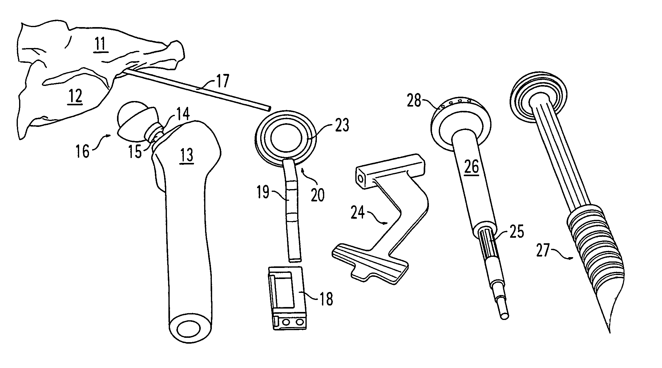
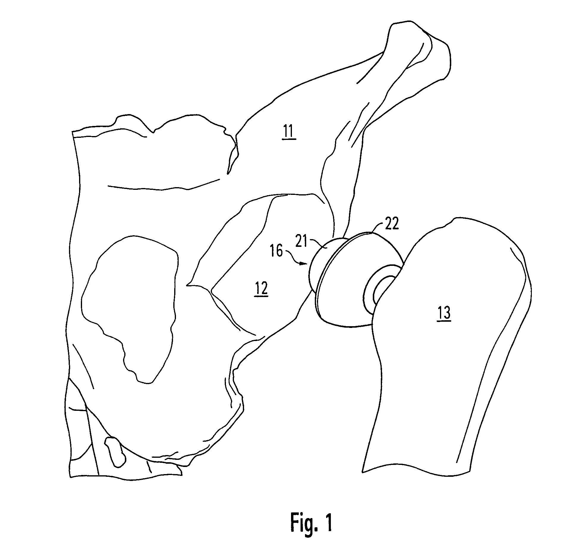
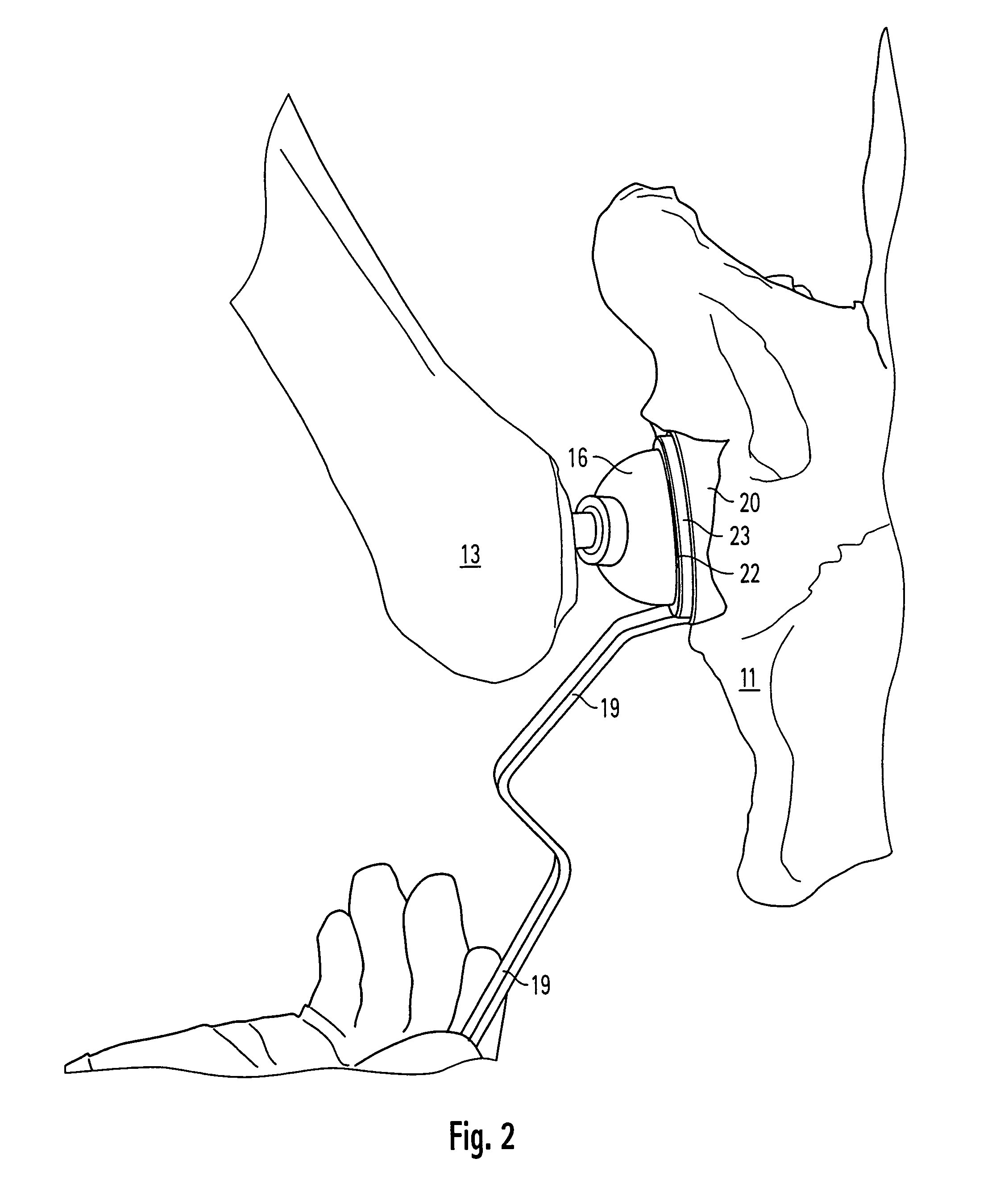
[0044]Prior to consideration of the individual steps, for a first exemplary embodiment the complete set of instruments for anatomically correct implantation of a hip-joint endoprosthesis will be described with reference to FIG. 10, which shows the following parts (from left to right):[0045]11 Pelvic bone[0046]12 Acetabulum[0047]13 Proximal section of a femur, within which a manipulation rasp (not shown in detail) is fixed[0048]14 Proximal end of the manipulation rasp placed within the femur[0049]15 Prosthesis neck[0050]16 Manipulation joint head set onto the prosthesis neck in the conventional way, in particular by means of a “stick-on cone” connection[0051]17 Guide rod anchored in the pelvic bone[0052]18 Guide block, which can be attached to a manipulation cup to accommodate the guide rod 17[0053]19 Manipulation cup with holder strap 19 for the guide block 18[0054]24 Orienting template[0055]25 Drive axle for milling cutter[0056]26 Axle bush[0057]27 Cup impact instrument[0058]28 Cut...


PUM


Abstract

Accessory for implantation of a hip joint endoprosthesis, with a manipulation cup, a manipulation joint head with means for orienting the manipulation cup in the acetabulum, and with a device to represent the correctly oriented position of the manipulation cup such that by means of this device a bone-milling cutter and an impact instrument can then oriented appropriately for placement of the prosthesis cup.

Description

RELATED APPLICATIONS[0001]This Application is a US National Phase of the International Application No. PCT / EP03 / 00035 filed Jan. 3, 2003 designating the US and published in German on Jul. 17, 2003 as WO 03 / 057087, which claims priority of German Patent Application No. 102 00 690.3, filed Jan. 10, 2002.FIELD OF THE INVENTION[0002]The invention relates to an accessory for implantation of a hip-joint endoprosthesis, as well as to a method for manipulating it, in particular for orienting a bone-milling cutter and an impact instrument to implant a prosthesis cup in the acetabulum.DESCRIPTION OF THE RELATED ART[0003]When hip endoprostheses are being inserted, the surgeon must proceed through various stages of the operation in which tools are employed; in particular, it is necessary to use a bone cutter in order to mill out the natural acetabulum and thus form a bearing socket within which an artificial cup can be anchored. An impact instrument is also used to drive the cup into place. Whe...

Claims


Application Information

Patent Timeline
IPC IPC(8): A61B17/58A61B17/17A61B90/00A61B90/50A61F2/32A61F2/34A61F2/36A61F2/46
CPCA61B19/26A61F2/4609A61F2/4684A61B17/1746A61B2019/467A61F2/32A61F2/34A61F2002/3611A61F2002/3625A61F2002/4668A61F2002/4681A61B19/201A61B2090/067A61B90/50A61B90/11
Inventor GRAF, REINHARDIMHOF, MARTINBRACK, RENE
Owner SMITH & NEPHEW ORTHOPAEDICS
Why Eureka
Try Eureka