

Transformer
a transformer and transformer technology, applied in the field of transformers, can solve the problems of reducing the volume and height of the transformer, failing to provide a compact device, and affecting the design of the transformer,
- Summary
- Abstract
- Description
- Claims
- Application Information
AI Technical Summary
Benefits of technology
Problems solved by technology
Method used
Image

Examples
first embodiment
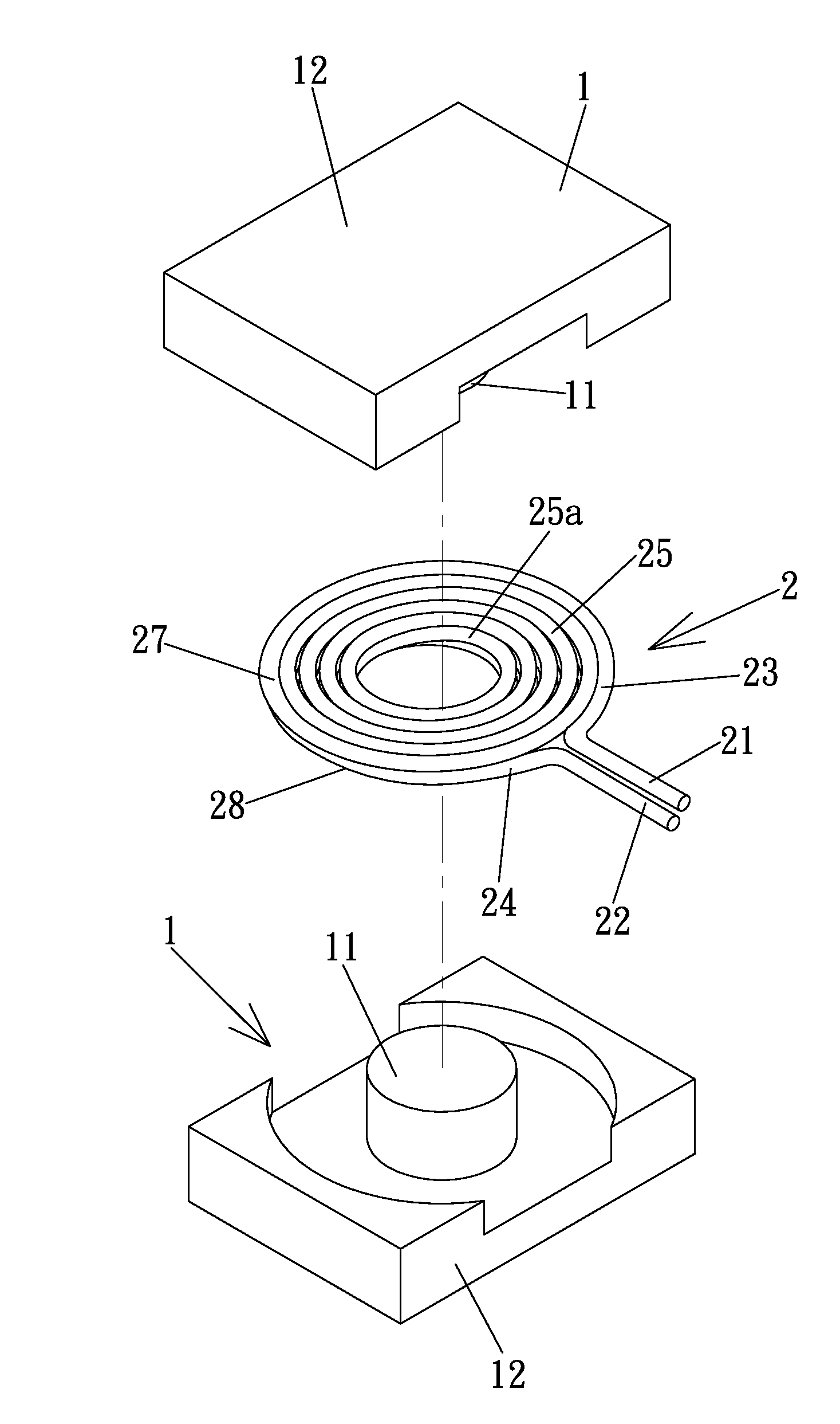
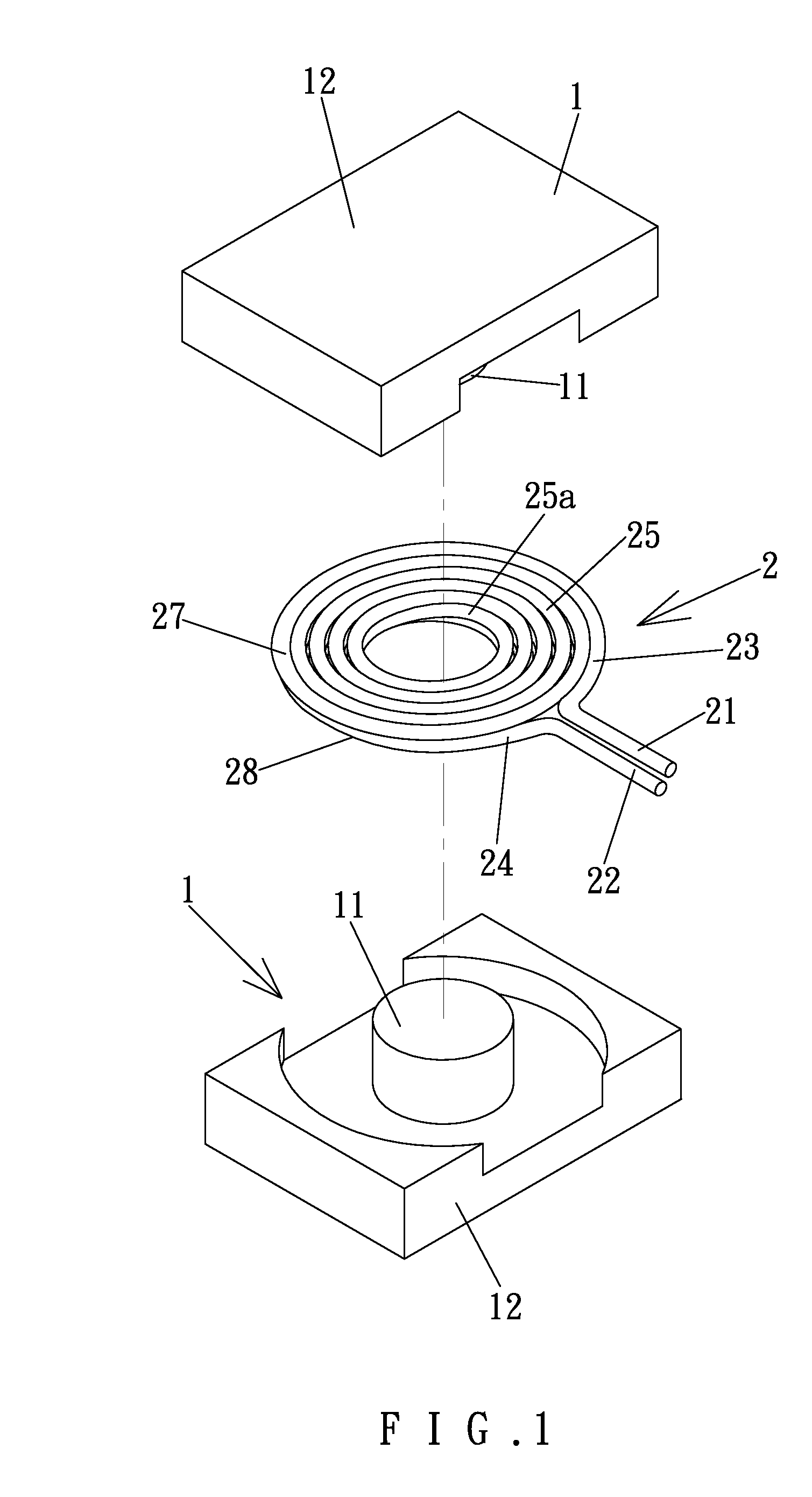
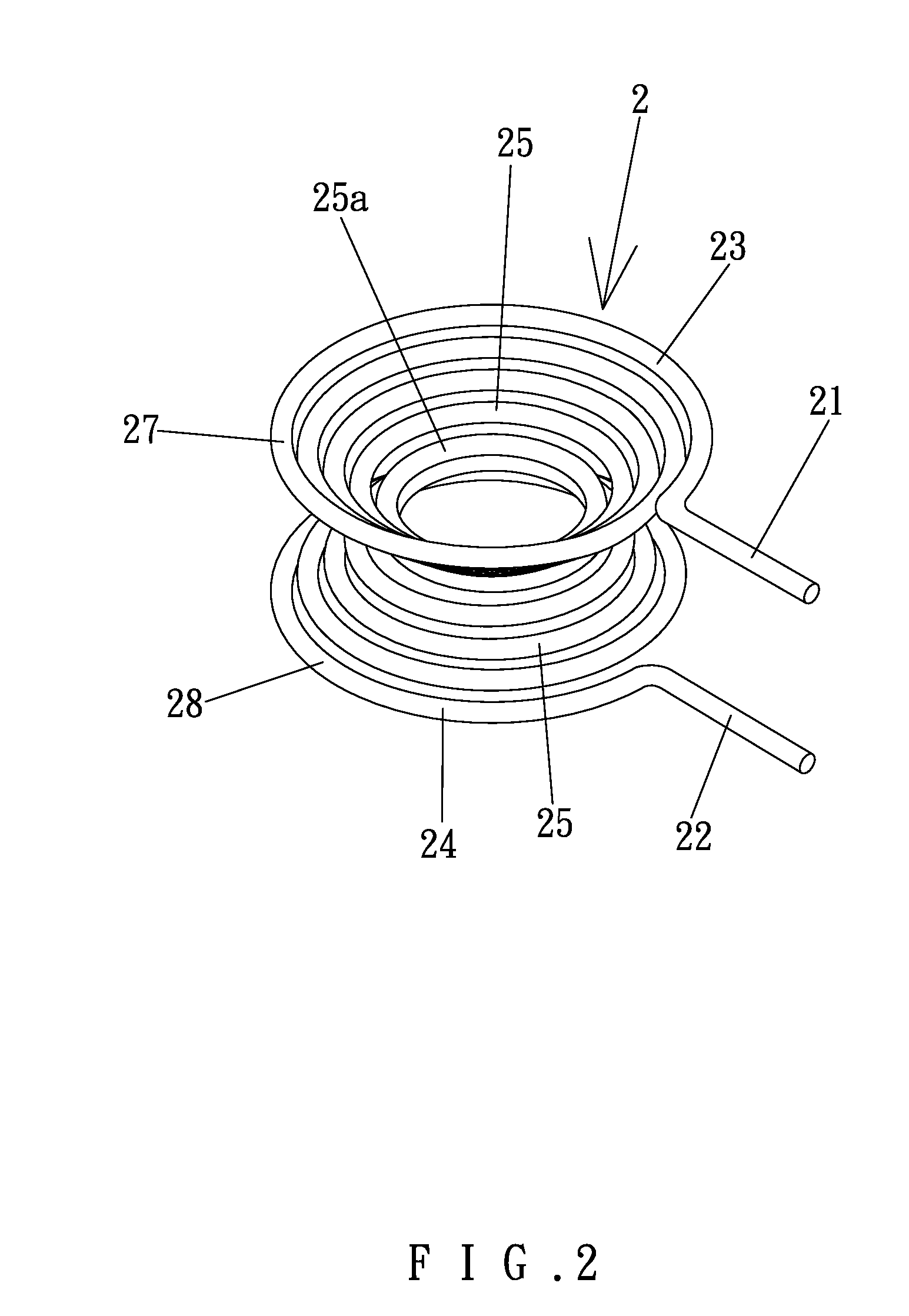
[0026]The coil modules 2 can include differing diameters according to design needs. The coil modules 2 can be stacked around the shaft 11 of the iron core 1 with the ends of the coil modules 2 interconnected to each other by series or parallel connection, so as to form transformers of isolated type, self-coupling type, or other types. FIGS. 3 and 4 show a transformer of a first embodiment according to the preferred teachings of the present invention. Specifically, the transformer shown in FIGS. 3 and 4 is of isolated type and includes primary and secondary windings 3 and 4. The primary winding 3 includes three coil modules 2, and the secondary winding 4 includes two coil modules 2, forming a voltage-decreasing transformer. One of the ends of each coil module 2 of the primary winding 3 is interconnected by an interconnecting section 31 to one of the ends of an adjacent coil module 2 of the primary winding 3. One of the ends of the coil modules 2 of the secondary winding 4 is intercon...
second embodiment
[0027]FIG. 5 shows a transformer of a second embodiment according to the preferred teachings of the present invention. The transformer of this embodiment is of isolated type and includes a primary winding 5 and a secondary winding 6. The primary winding 5 includes two coil modules 2 interconnected by an interconnecting portion 31 and spaced from each other along the axis of the shaft 11 of the iron core 1 by a spacing 32. The secondary winding 6 includes a coil module 2′ received in the spacing 32 between the coil modules 2 of the primary winding 5. The primary and secondary windings 5 and 6 are intermediate the bases 12 of the iron core 1 along the axis. The coil module 2 of the secondary winding 6 has a wire diameter larger than the coil modules 2 of the primary winding 5. The wire diameters of the transformer according to the teachings of the present invention can be varied according to design needs.
third embodiment
[0028]FIG. 6 shows a transformer of a third embodiment according to the preferred teachings of the present invention. The transformer of this embodiment is of self-coupling type and includes two coil modules 2 interconnected by a conductive member 7. Specifically, the lower end 22 of the upper coil module 2 is connected by the conductive member 7 to the upper end 21 of the lower coil module 2. A connection line 29 is coupled to the conductive member 7. The coil modules 2 are intermediate the bases 12 of the iron core 1 along the axis. The upper end 21 of the upper coil module 2 and the lower end 22 of the lower coil module 2 together define a primary side connection. The connection line 29 and the lower end 22 of the lower module 2 together define a secondary side connection.
PUM
| Property | Measurement | Unit |
|---|---|---|
| diameters | aaaaa | aaaaa |
| diameter | aaaaa | aaaaa |
| conductive | aaaaa | aaaaa |
Abstract
Description
Claims
Application Information