Method and apparatus for directional networking topology management

a topology management and directional networking technology, applied in the field of communication systems, can solve the problems of limited transmission power, limited number of neighboring devices, and limited transmission power to reduce the impact of other messages received,

Inactive Publication Date: 2010-11-09
THE BOEING CO
View PDF4 Cites 34 Cited by
  • Summary
  • Abstract
  • Description
  • Claims
  • Application Information

AI Technical Summary

Problems solved by technology

Transmission power is limited to allow simultaneous transmissions to increase spatial reuse and minimize power consumption.
The transmission power also is limited to reduce the impact on reception of other messages by other nodes.
Increasing the number of neighbor nodes may unacceptably reduce the capacity of the network.
Forming a link with the different potential neighbor nodes may have a number of different costs.
These exchanges may reduce the throughput available for communications between the nodes.
Further, if the time schedule is quantized into relatively large slots to allow the abstraction of variable signal time of flight, then allocating a large slot to links that have little or no data flow may result in a waste of resources in the network.
If each node has many links, the overhead associated with this type of reporting may be unduly burdensome with respect to network resources.
If only a few links are actually handling traffic, scheduling unnecessary transmissions also may increase the delay in transmitting data.
This situation may result in an increase in the per-hop latency within the network.
Further, with many transmissions in various directions, interference may occur with respect to third parties that are not part of the communications.
This type of interference may increase with long range and / or high power transmissions and may reduce the resources available to carry data within a network.

Method used


Image

  • Method and apparatus for directional networking topology management
  • Method and apparatus for directional networking topology management
  • Method and apparatus for directional networking topology management

Examples


Embodiment Construction

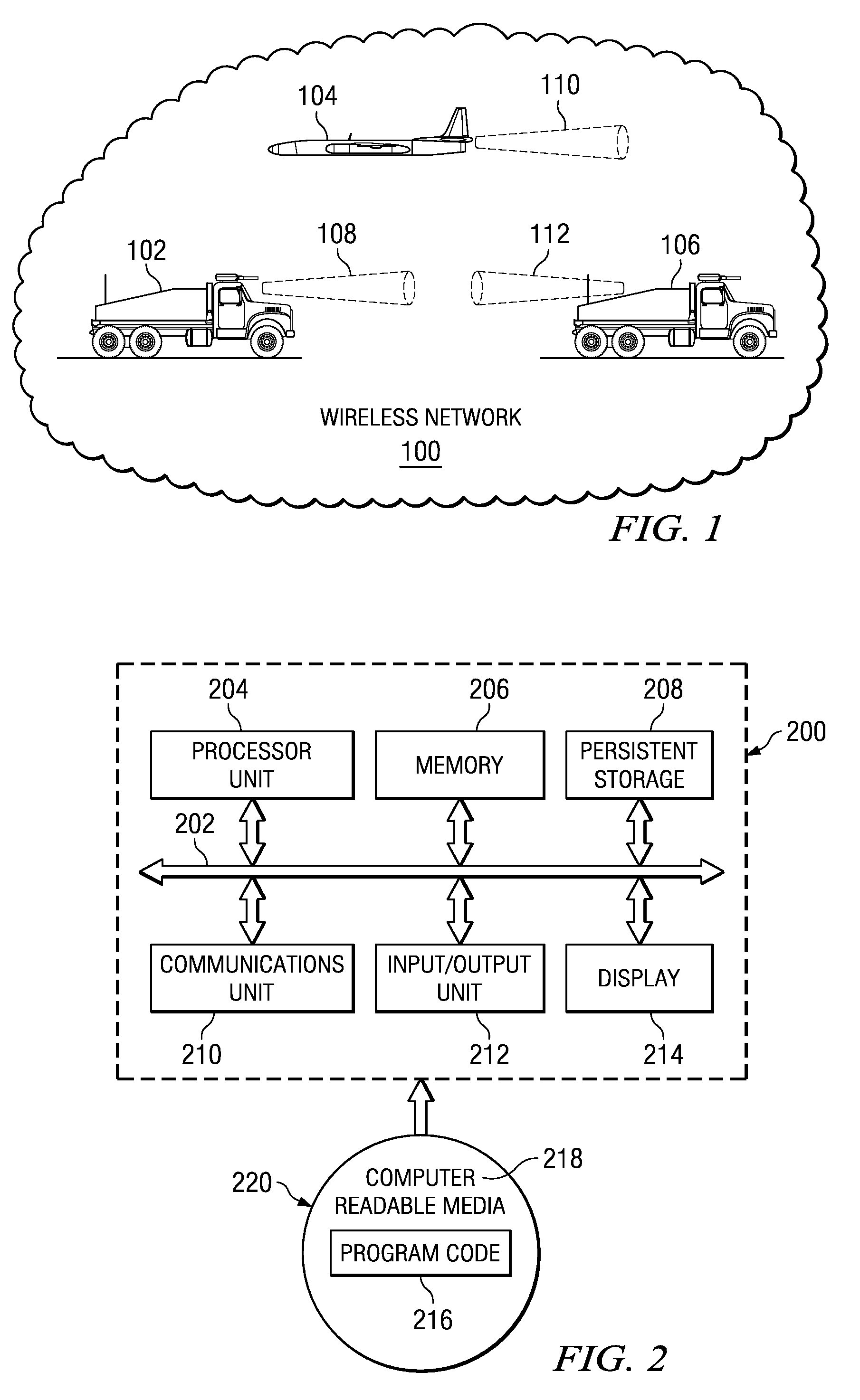
[0042]With reference now to the figures and in particular with reference to FIG. 1, a diagram illustrating a wireless network environment is depicted in accordance with an advantageous embodiment. In this example, wireless network 100 contains nodes 102, 104, and 106. These nodes are mobile nodes within wireless network 100. Nodes 102 and 106 are ground vehicles, while node 104 is an aircraft. Nodes 102, 104, and 106 may be located in various geographic locations.

[0043]Wireless network 100 may be, for example, an ad hoc network. An ad hoc network is a network that may be dynamically formed among a group of nodes and requires no existing structure or preconfiguration. An ad hoc network is dynamic and self organizing in nature. These types of features make this type of network particularly useful in situations in which rapid network deployments are required.

[0044]In this example, nodes 102, 104, and 106 employ directional links. These nodes are all capable of communicating with each o...


PUM


Abstract

A computer implemented method, apparatus, and computer program product to managing links in a network. A directional link management system comprises a network manager, a router, a situational awareness database, a neighbor discovery module, a topology manager, and a data link manager. The network manager provides performance parameters for a wireless network. The router routes information to neighbor nodes provides information about links between nodes in the wireless network environment. The situational awareness database stores information about the nodes. The neighbor discovery module detects a presence of a new node. The topology manager identifies a set of links for a node using the set of performance parameters, information about the links, and information about the nodes. The data link manager manages the identified links.

Description

BACKGROUND INFORMATION[0001]1. Field[0002]The present disclosure relates generally to communications systems and in particular to a method and apparatus for managing communications between data processing systems. Still more particularly, the present disclosure relates to a method, apparatus, and computer program code for managing directional network links in a communications system.[0003]2. Background[0004]Internet protocols were originally designed for what is referred to as the “wired” Internet. In this environment, physical links exist between routers and other devices in this type of network. Few decisions are to be made about the topology for this type of network except for the original setup or design of these links.[0005]More recently, protocol development has moved to the direction of omni directional wireless networks. In order for a receiver to quickly decode a packet with this type of network, only one transmitter can use a particular frequency and code at a time within ...

Claims


Application Information

Patent Timeline
Patent Type & Authority Patents(United States)
IPC IPC(8): H04L12/28
CPCH04L45/02H04W40/246
Inventor DUKE, MARTIN HUYNHPEI, GUANGYU
Owner THE BOEING CO
Why Eureka
Try Eureka