
Systems for scheduling the transmission of data in a network device

a network device and data scheduling technology, applied in the field of data transfer, can solve the problems of router performance degradation, router failure to handle traffic at line rate, and general purpose processors cannot scale to meet these new demands

Active Publication Date: 2010-11-09
JUMIPER NETWORKS INC
View PDF11 Cites 45 Cited by
  • Summary
  • Abstract
  • Description
  • Claims
  • Application Information

AI Technical Summary

Benefits of technology

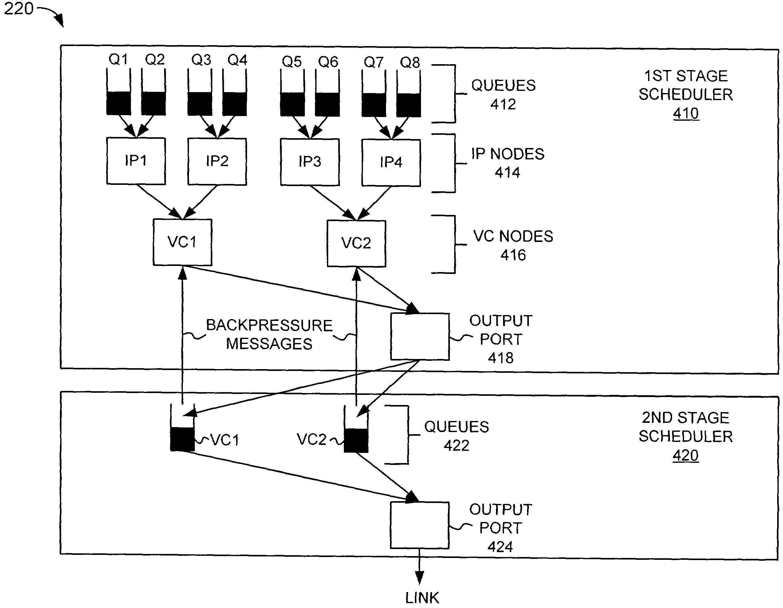
[0015]An eighth aspect consistent with the principles of the invention is directed to a method for scheduling data units for transmission by a network device. The method includes providing a first scheduler for performing quality of service (QoS) scheduling of data units, transferring the QoS-scheduled data units to a second scheduler, and performing shaping in the second scheduler.

Problems solved by technology

As line rates and traffic volume increased, however, general purpose processors could not scale to meet these new demands.
For example, as functionality was added to the software, such as accounting and policing functionality, these routers suffered performance degradation.
In some instances, the routers failed to handle traffic at line rate when the new functionality was turned on.
Conventional SARs do not provide, however, quality of service (QoS) scheduling, such as weighted round robin scheduling, per-packet strict priority scheduling, hierarchical virtual path-virtual circuit scheduling, and the like, which are desirable to Internet Service Providers (ISPs).

Method used


Image

  • Systems for scheduling the transmission of data in a network device
  • Systems for scheduling the transmission of data in a network device
  • Systems for scheduling the transmission of data in a network device

Examples


Embodiment Construction

[0024]The following detailed description of the invention refers to the accompanying drawings. The same reference numbers in different drawings may identify the same or similar elements. Also, the following detailed description does not limit the invention. Instead, the scope of the invention is defined by the appended claims and equivalents.

[0025]As described herein, a first stage scheduler and a second stage scheduler are used to improve the scheduling of data units in a network device.

System Configuration

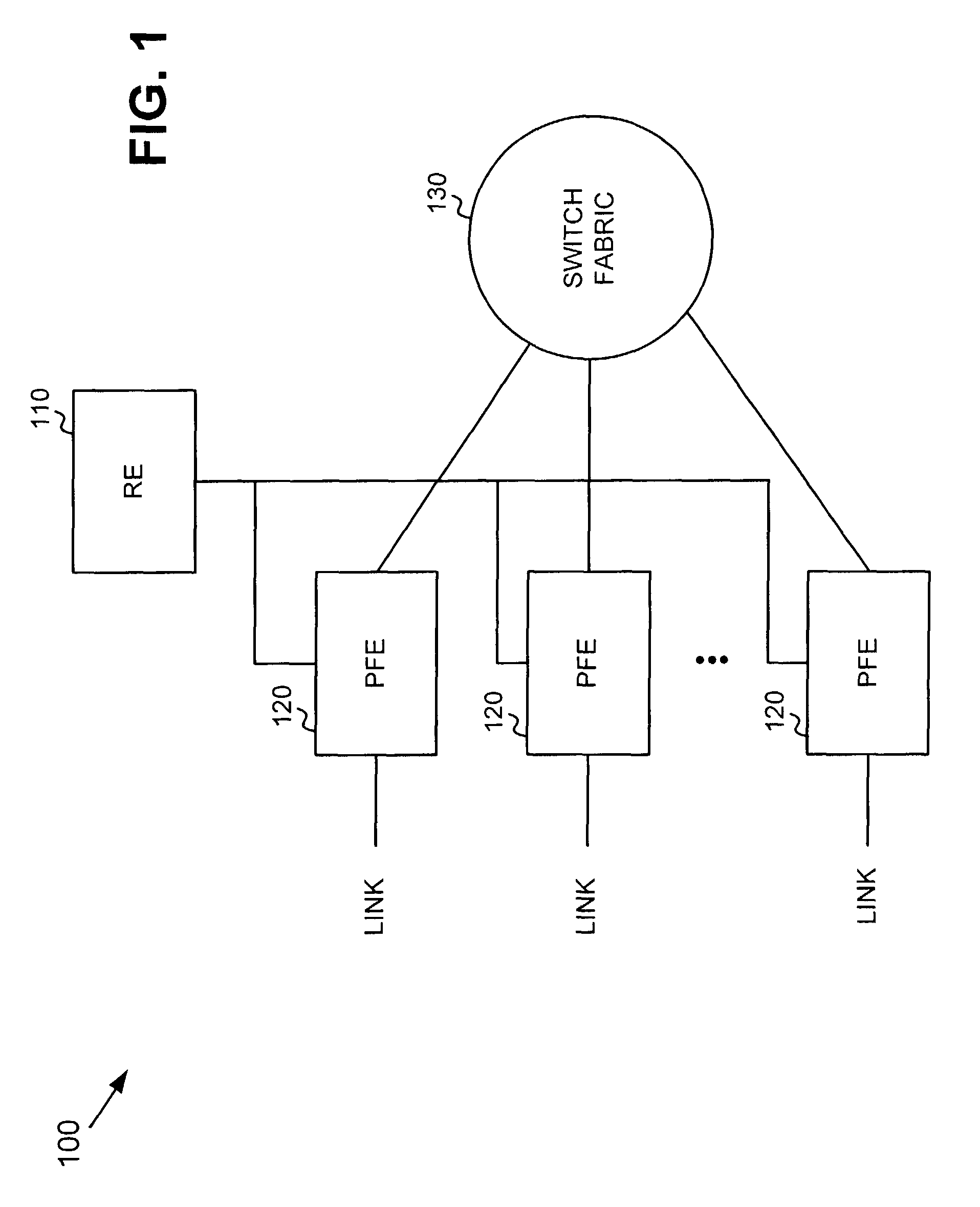
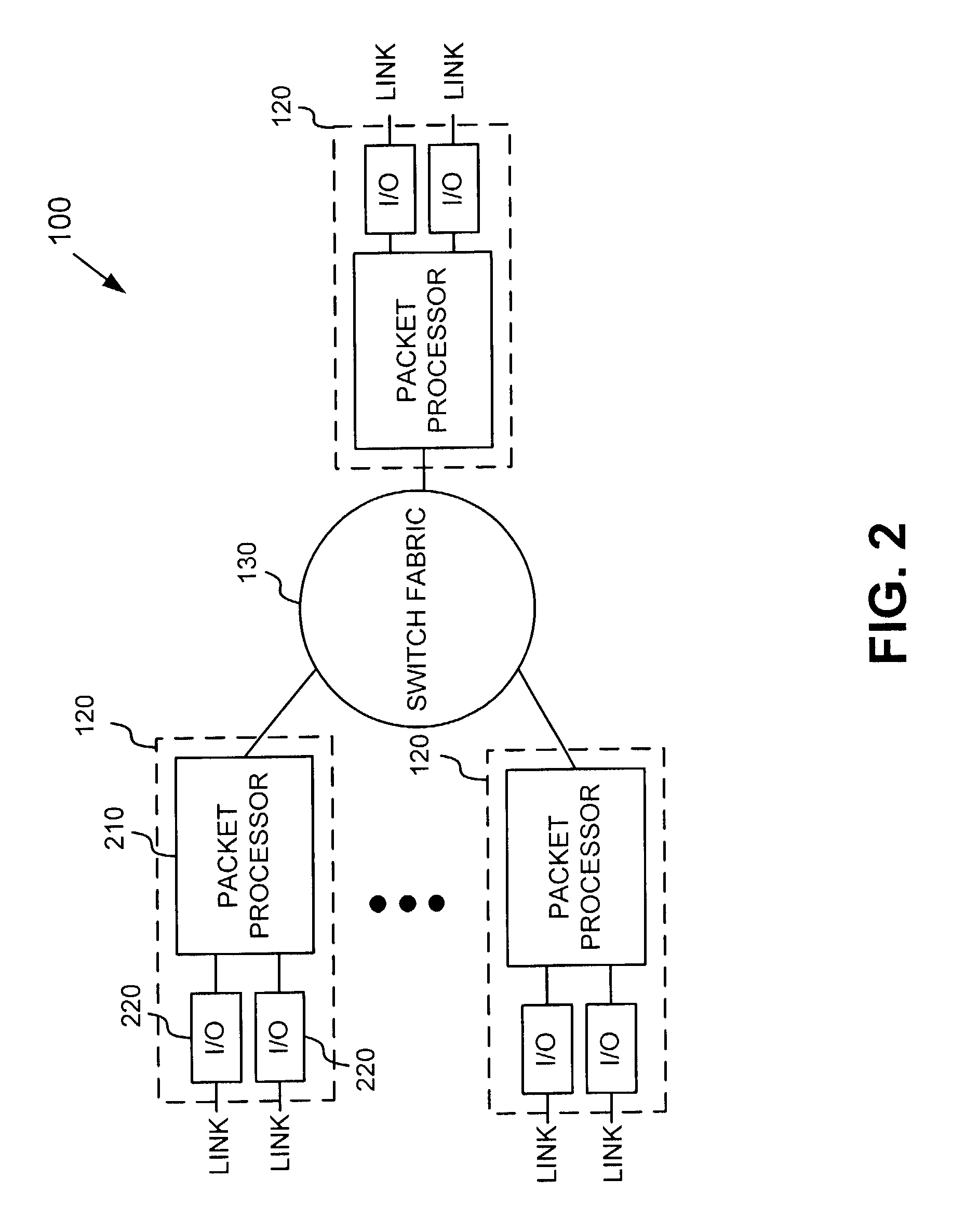
[0026]FIG. 1 is a block diagram illustrating an exemplary routing system 100 in which systems and methods consistent with the principles of the invention may be implemented. System 100 receives one or more packet streams from a physical link, processes the packet stream(s) to determine destination information, and transmits the packet stream(s) out on a link in accordance with the destination information. System 100 may include a routing engine (RE) 110, packet forwarding engines...


PUM


Abstract

In a network device, a line card includes a first scheduler configured to perform scheduling for data units of a first type and a second scheduler that is connected in series to the first scheduler and configured to perform scheduling for data units of a second type. The schedulers may be configured in a variety of ways to achieve certain data unit flow characteristics.

Description

BACKGROUND OF THE INVENTION[0001]1. Field of the Invention[0002]The present invention relates generally to data transfer, and more particularly, to systems for scheduling the transmission of data in a network device.[0003]2. Description of Related Art[0004]Routers receive data on a physical media, such as optical fiber, analyze the data to determine its destination, and output the data on a physical media in accordance with the destination. Routers were initially designed using a general purpose processor executing large software programs. As line rates and traffic volume increased, however, general purpose processors could not scale to meet these new demands. For example, as functionality was added to the software, such as accounting and policing functionality, these routers suffered performance degradation. In some instances, the routers failed to handle traffic at line rate when the new functionality was turned on.[0005]To meet the new demands, purpose-built routers were designed...

Claims


Application Information

Patent Timeline
Patent Type & Authority Patents(United States)
IPC IPC(8): H04L12/56
CPCH04L47/60H04L49/90H04L47/623H04L47/6275H04L47/6295
Inventor LEMAIRE, THOMASSIU, DANIEL K.PATNAUDE, JR., ALBERT E.
Owner JUMIPER NETWORKS INC
Learn More