Deep well direct expansion heating and cooling system

a technology of heating and cooling system and deep well, which is applied in the direction of domestic cooling apparatus, heat pumps, lighting and heating apparatus, etc., can solve the problems of common under-sizing of direct expansion system, reduce overall heating system operational efficiency, increase heat conductivity rate, and reduce water pump operation power requirements

Inactive Publication Date: 2010-11-16
EARTH TO AIR SYST
View PDF57 Cites 37 Cited by
  • Summary
  • Abstract
  • Description
  • Claims
  • Application Information

AI Technical Summary

Benefits of technology

[0043]Consequently, in a DWDX application, the refrigerant transport tubing, which may, or may not, have been pre-inserted into a containment watertight pipe, should be lowered into the well / borehole by means of a rope, such as a nylon rope, a polypropylene rope, a wire rope, a steel cable, or the like. The rope is attached to the lower base segment of the refrigerant transport tubing to be lowered into the well / borehole, with the rope being fed down into the borehole along with the refrigerant transport tubing during system installation. If necessary during system installation, the refrigerant transport tubing can be easily raised, and then re-lowered, by means of the rope attached to the lower end of the refrigerant transport tubing being inserted into the borehole.
[0131]Since the oil exiting the compressor and entering the oil separator has been superheated via the compression of the hot refrigerant vapor, the design improvement of directing the superheated oil into the accumulator, or into the suction line prior to the accumulator, serves to materially assist in vaporizing any accumulated liquid refrigerant, with the superheated oil being returned to the compressor via the small suction hole in the said vapor intake tube located within, and proximate to the bottom of, the accumulator.

Problems solved by technology

The potential for under-sizing direct expansion systems commonly exists because system sizes are typically calculated via ACCA Manual J heating and cooling design criteria, ASHRAE design criteria, or other similar load design criteria, based upon temperature factors which cover 97.5% of the heating / cooling hours, which is not intended to accommodate all heating and cooling loads.

Method used


Image

  • Deep well direct expansion heating and cooling system
  • Deep well direct expansion heating and cooling system
  • Deep well direct expansion heating and cooling system

Examples


Embodiment Construction

[0146]The following detailed description is of the best presently contemplated mode of carrying out the invention. The description is not intended in a limiting sense, and is made solely for the purpose of illustrating the general principles of the invention. The various features and advantages of the present invention may be more readily understood with reference to the following detailed description taken in conjunction with the accompanying drawings.

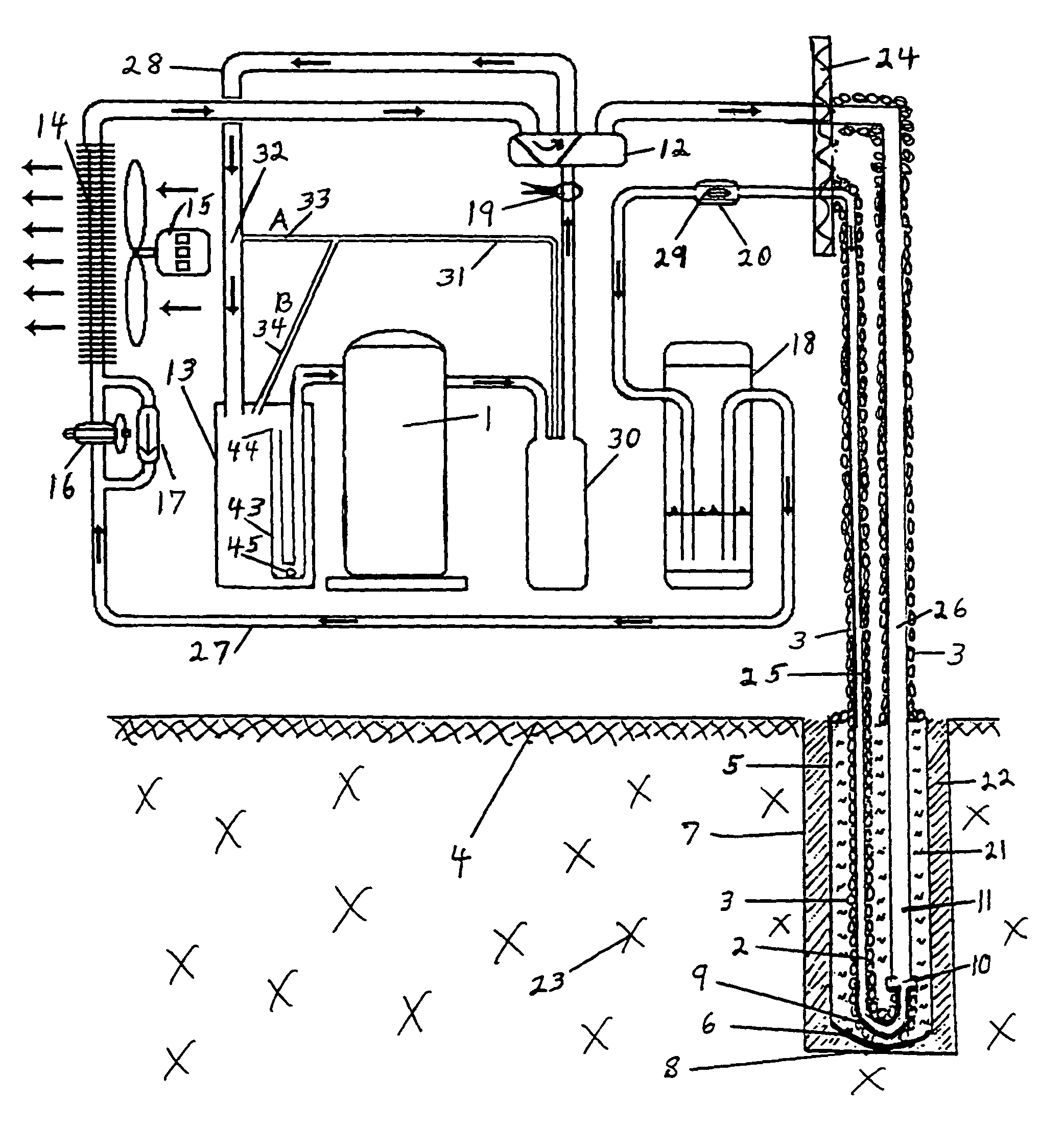
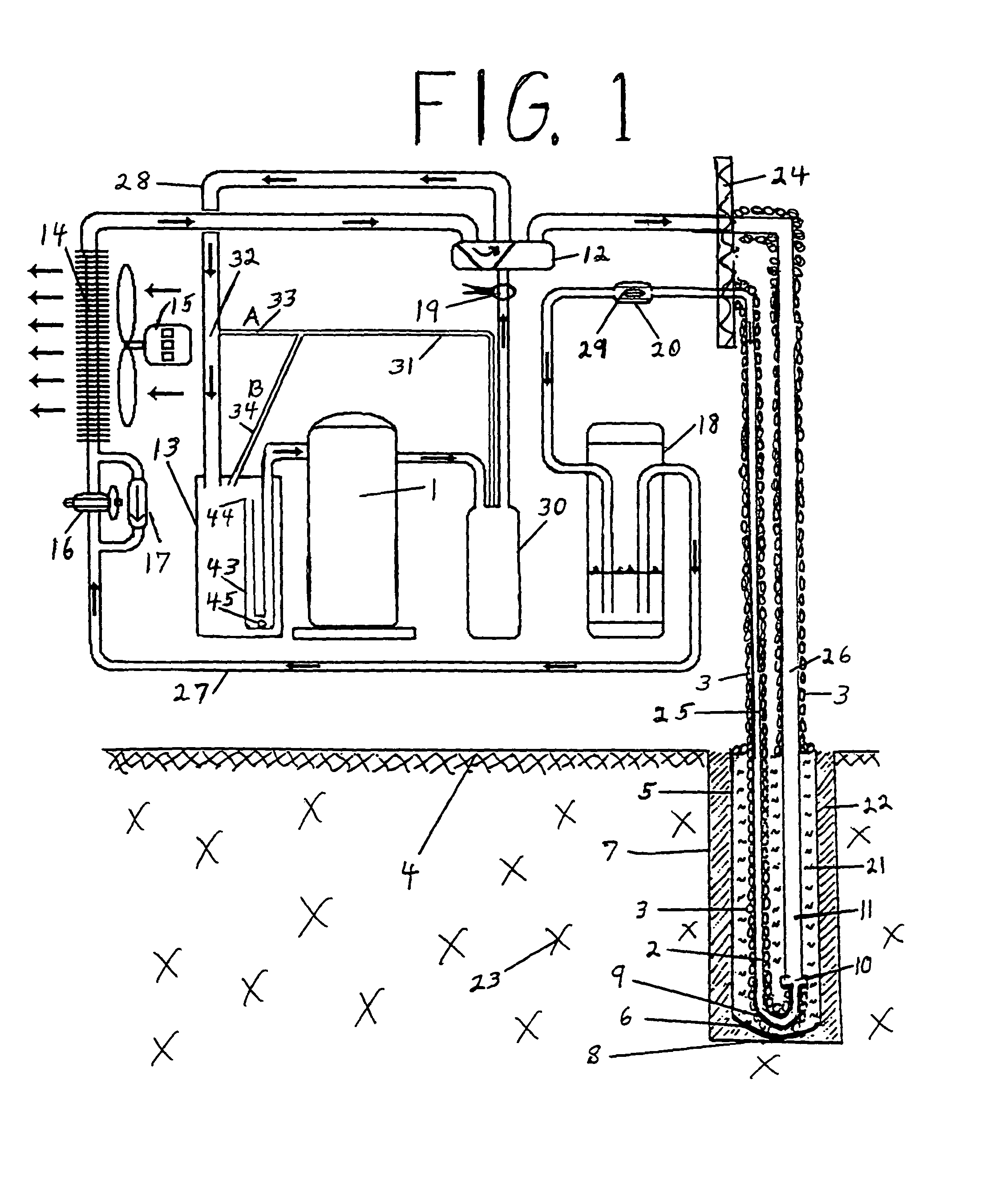
[0147]Referring now to the drawings in detail, where like numerals refer to like parts or elements, there is shown in FIG. 1 a side view of a simple version of a deep well direct expansion geothermal heat pump system, operating in a cooling mode.

[0148]A refrigerant fluid (not shown) is transported, by means of a compressor's 1 force and suction, inside a larger diameter un-insulated sub-surface refrigerant vapor transport / heat exchange line tube 11, which is located below the ground surface 4 within a heat conductive, watertight pipe ...


PUM


Abstract

A direct expansion geothermal heat exchange system including certain requisite heating / cooling load calculations, certain operational refrigerant pressures, refrigerant tubing design lengths in varying soils, refrigerant tubing sizing per ton of system design capacity, refrigerant tubing sizing at varying sub-surface installation depths, lowering refrigerant tubing into a borehole via rope, encasing the lower segment of refrigerant tubing within a solid encasement, providing a bar for rope attachment, using a winch to raise and lower refrigerant tubing, certain sizing of the compressor, certain air handler sizing, certain accumulator sizing, certain sizing of metering devices in the heating mode and in the cooling mode, parameters for charging the system, certain sizing of the receiver, utilizing certain grout for corrosion protection and for enhanced heat transfer, providing a fluid filled pipe within a borehole to contain accessible refrigerant tubing, providing a certain fluid fill for the pipe, one of providing a certain time delay on the low pressure cut off switch and of eliminating the switch, providing a certain oil separator return line location, and providing a certain amount of lubricating oil.

Description

CROSS-REFERENCES TO RELATED APPLICATIONS[0001]This application is a Non-Provisional Utility application which claims benefit of co-pending U.S. Provisional Patent Application Ser. No. 60 / 439,831 filed Jan. 14, 2003, entitled “Deep Well Direct Expansion Heating and Cooling System” which is hereby incorporated by reference.[0002]A portion of the disclosure of this patent document contains material that is subject to copyright protection. The copyright owner has no objection to the facsimile reproduction by anyone of the patent document or the patent disclosure, as it appears in the U.S. Patent and Trademark Office patent file or records, but otherwise reserves all copyright rights whatsoever.STATEMENT REGARDING FEDERALLY SPONSORED RESEARCH OR DEVELOPMENT[0003]Not ApplicableREFERENCE TO SEQUENCE LISTING OR COMPUTER PROGRAM LISTING APPENDIX[0004]Not ApplicableBACKGROUND OF THE INVENTION[0005]The present invention relates to an improved sub-surface, or in-ground / in-water, direct expansio...

Claims


Application Information

Patent Timeline
Patent Type & Authority Patents(United States)
IPC IPC(8): F25B45/00
CPCF24J3/083F24J3/086F25B13/00F25B30/06F25B2313/02741Y02E10/125Y02E10/16F25B2500/01F24T10/15F24T10/30Y02E10/10
Inventor WIGGS, B. RYLAND
Owner EARTH TO AIR SYST
Why Eureka
Try Eureka