Firearm suppressor

Inactive Publication Date: 2010-11-16
STANOWSKI DAVID
View PDF21 Cites 106 Cited by
  • Summary
  • Abstract
  • Description
  • Claims
  • Application Information

AI Technical Summary

Benefits of technology

[0009]And another object of the invention is to provide

Problems solved by technology

Each of these effects can be undesirable for reasons of accuracy, secrecy and general safety to the operator.
Muzzle jump or recoil can adversely impact accuracy and reduce the rate of delivery of projectiles on target accurately.
The noise can be damaging to the operator or nearby individuals not wearing ear protectors and can bring unwanted attention in instances of covert use.
The flash also can adversely affect night vision and draw unwanted attention to the use of

Method used


Image

  • Firearm suppressor
  • Firearm suppressor
  • Firearm suppressor

Examples


Embodiment Construction

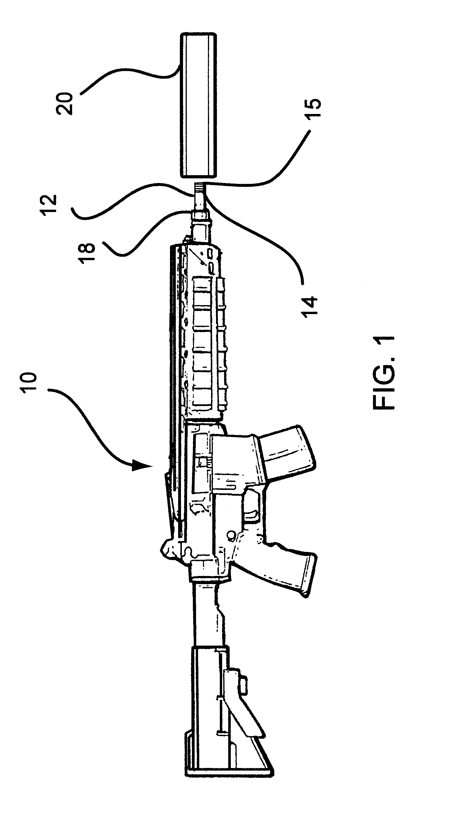
[0024]Turning now to the drawings in which like reference characters indicate corresponding elements throughout the several views, attention is first directed to FIG. 1, which illustrates a firearm 10 including a barrel 12 having a muzzle 14 and a bore 15. A suppressor 20, according to the present invention, is coupled to muzzle 14 of firearm 10. Firearm 10 includes substantially any small arms, such as bolt action rifles, automatic and semiautomatic rifles, and heavier firearms such as machines guns and the like. Substantially any firearm with a barrel having a muzzle and propelling a projectile therefrom with combusted propellant gasses can employ suppressor 20.

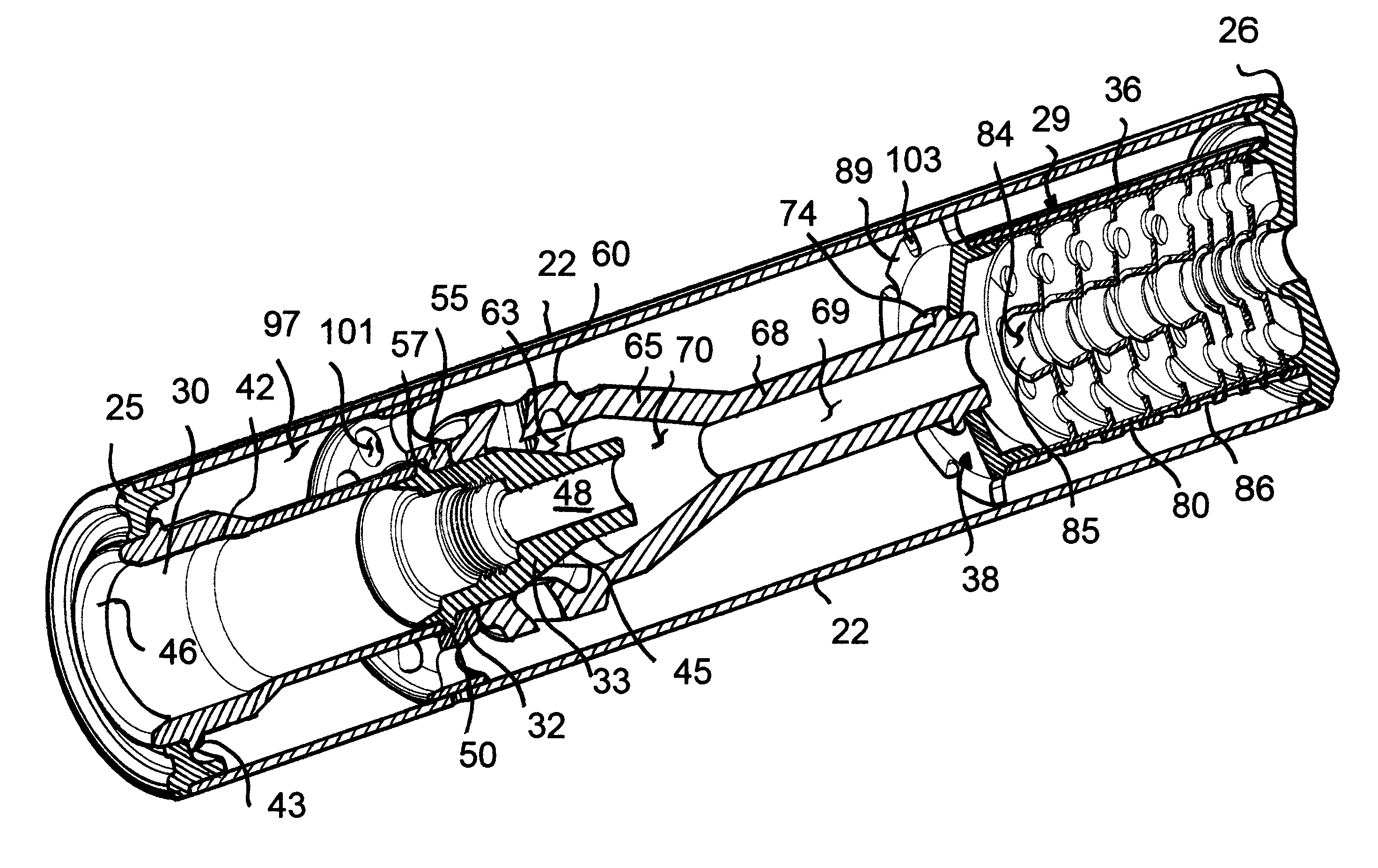
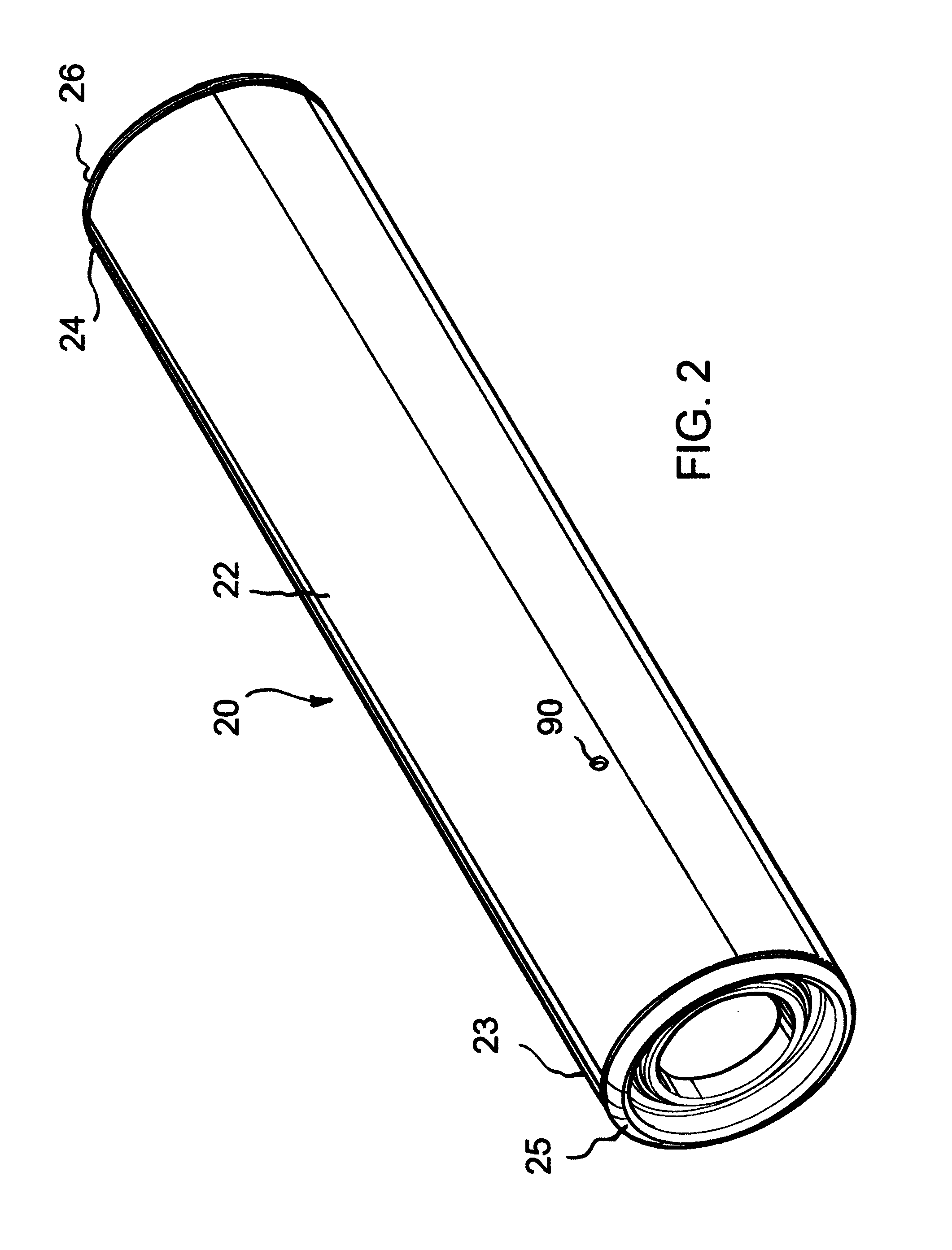
[0025]Referring now to FIG. 2, suppressor 20 includes an outer casing 22 having a rearward end 23 and a forward end 24. For purposes of this description, the term rearward is a direction toward the firearm, and the term forward is a direction away from the firearm. A rearward end cap 25 and forward end cap 26 close rearward...


PUM


Abstract

A suppressor for use with a firearm having a barrel with a muzzle and a bore, the suppressor includes an outer casing having a rearward end and a forward end, an evacuator assembly for receiving the muzzle of the firearm carried by the outer casing, and an expansion chamber defined between the outer casing and the evacuator assembly in gaseous communication with an interior volume of the evacuator assembly.

Description

FIELD OF THE INVENTION[0001]This invention relates to firearms.[0002]More particularly, the present invention relates to suppressors for reducing muzzle blast in firearms.BACKGROUND OF THE INVENTION[0003]It is well known in the field of firearms to modify barrels to compensate for various effects of firing a projectile using propellant gasses generated from the combustion of a propellant. Some of the effects are muzzle jump and / or recoil and muzzle blast. Each of these effects can be undesirable for reasons of accuracy, secrecy and general safety to the operator. Muzzle jump or recoil can adversely impact accuracy and reduce the rate of delivery of projectiles on target accurately. Muzzle blast is a loud noise and flash generally accompanying the discharge of a firearm. The combusted propellant gasses leaving the muzzle behind the projectile produce a loud bang and a flash. The noise can be damaging to the operator or nearby individuals not wearing ear protectors and can bring unwan...

Claims


Application Information

Patent Timeline
IPC IPC(8): F41A21/34
CPCF41A21/30F41A21/325F41A21/34
Inventor DAVIES, ROBERT B.
Owner STANOWSKI DAVID
Why Eureka
Try Eureka