Improved method for making vacuum switch device

A technology of vacuum switch and vacuum pump, which is applied in the direction of electric switch, high voltage/high current switch, high voltage air circuit breaker, etc. It can solve the problems of high investment, high product cost, long process time, etc.

Inactive Publication Date: 2008-08-06
开关工艺欧洲有限公司
View PDF0 Cites 6 Cited by
  • Summary
  • Abstract
  • Description
  • Claims
  • Application Information

AI Technical Summary

Problems solved by technology

[0007] The prior art has high investment,...

Method used


Image

  • Improved method for making vacuum switch device
  • Improved method for making vacuum switch device
  • Improved method for making vacuum switch device

Examples


Embodiment Construction

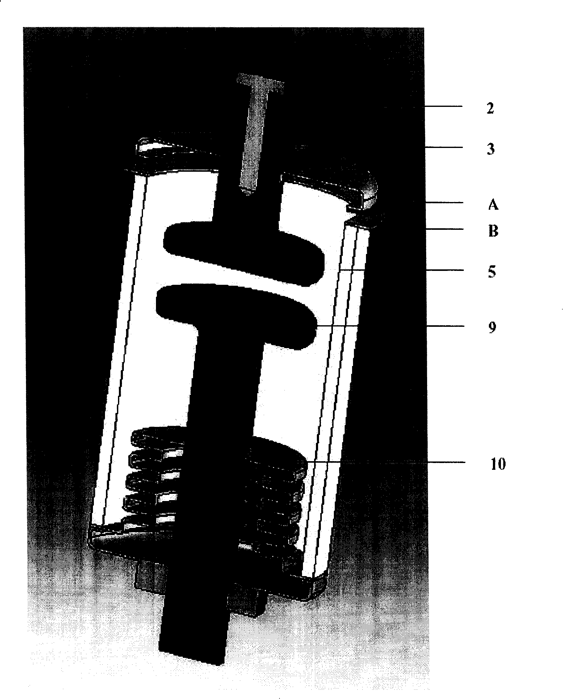
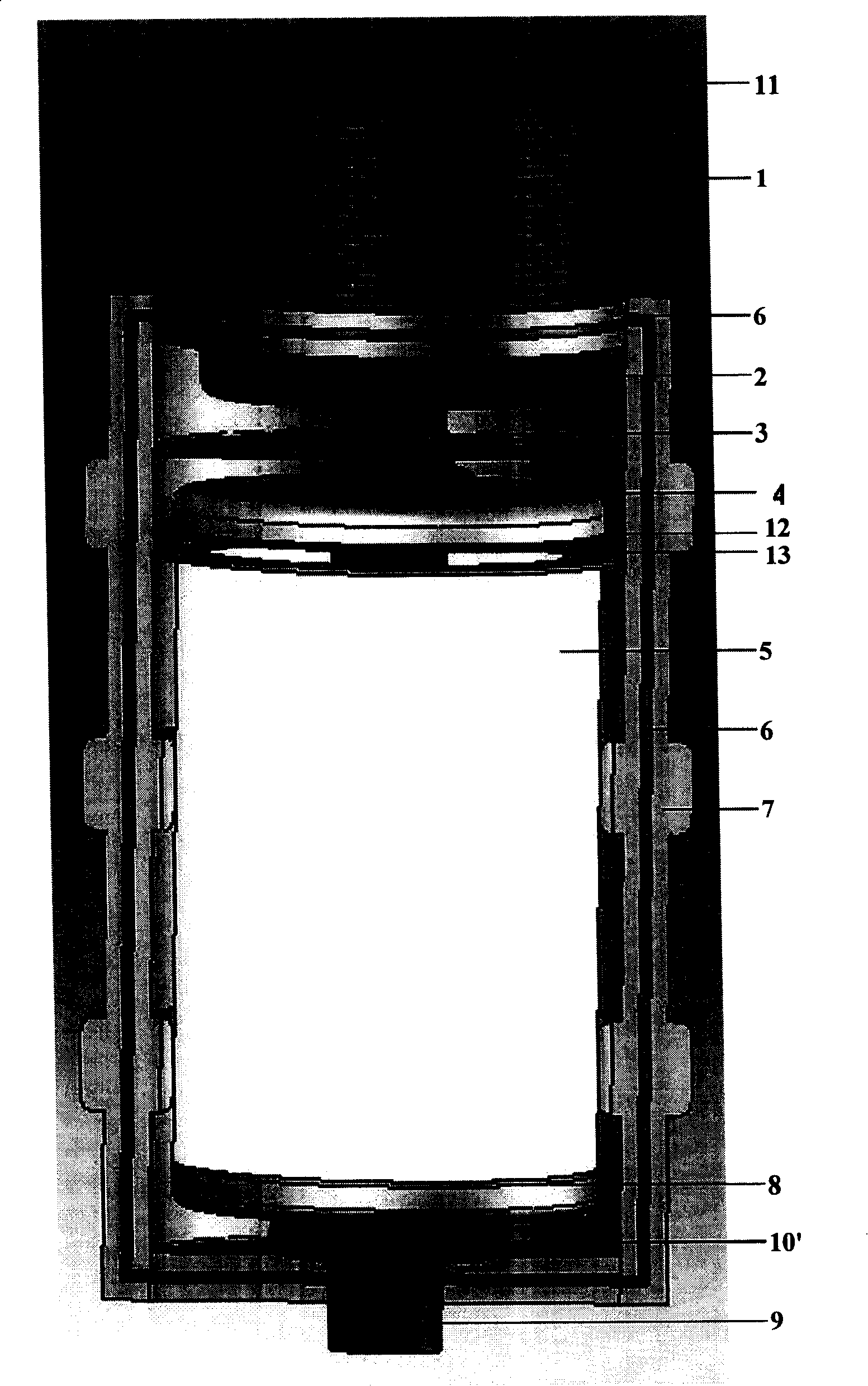
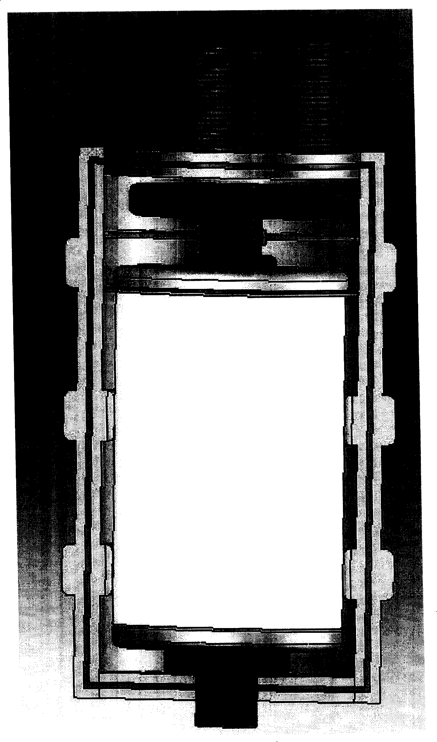
[0045] For this new method a small evacuated container is used, the inner dimensions of which only slightly exceed the outer dimensions of the vacuum chamber being evacuated.

[0046] These containers are connected to the high-efficiency vacuum pump with suitable hoses or pipes. These pumps can evacuate the vessel to the required vacuum within minutes while heating the vessel to 350°C to 400°C to remove all water molecules from the interior. In addition to chromium and copper, many conductor materials are allowed at this temperature.

[0047] All parts can be welded or soldered in advance, so only the two main parts are fed into the evacuated container for final welding.

[0048] The vessel consists of two or more parts which can be closed by bringing them together after the parts of the vacuum chamber have been brought in (see figure 1 , container open).

[0049] The parts are fed into one of the container segments in the correct order, where they are supported by fixtures...


PUM


Abstract

The invention provides a method for improving the manufacturing of a vacuum switching device. The method adopts a smaller evacuator which can work for a long time at a high temperature; in a minitype evacuating container, parts are kept separated by the magnetic force or corrugated pipes; once the container is evacuated, the needed high vacuum is obtained, and the magnetic polarity is converted, thereby the vacuum switching device is closed; in the process of the inner-part rolling seam welding(without welding blocks) or the induction heating(with welding blocks), the vacuum switching device is hermetically sealed, and the vacuum in the vacuum switching device is sealed in the vacuum switching device.

Description

technical field [0001] The invention relates to a method for manufacturing a vacuum switchgear. Background technique [0002] A high vacuum is required in the chamber of the vacuum chamber for the vacuum circuit breaker. In addition to conditioning the vacuum chamber with getters, the fabrication method itself is also very important. [0003] Currently, the state of the art already employs a one-shot soldering manufacturing method, in which the raw chamber is placed in a special large vacuum oven, where it remains for several hours. Once the desired temperature has been reached, the solder block placed between the objects to be welded, together with the distance holder, is melted by adjusting the temperature, if necessary, in several steps with different temperatures, until all the original open space is covered by the solder block Filled, some fragments and ingredients have been lowered into the block, thereby sealing the vacuum chamber hermetically. The external vacuum ...

Claims


Application Information

Patent Timeline
IPC IPC(8): H01H33/66H01H11/00
Inventor 郎德薄槐夏
Owner 开关工艺欧洲有限公司
Why Eureka
Try Eureka