Time-delayed gun bore evacuator

a technology of evacuating gun bores and gun tubes, which is applied in the field of large caliber gun tubes, can solve the problems of affecting the effective evacuation of gun bores, affecting the safety of crew members, etc., and achieves the effect of effective bore evacuation

Inactive Publication Date: 2013-10-29
UNITED STATES OF AMERICA THE AS REPRESENTED BY THE SEC OF THE ARMY
View PDF17 Cites 7 Cited by
  • Summary
  • Abstract
  • Description
  • Claims
  • Application Information

AI Technical Summary

Benefits of technology

[0014]It is an object of the invention to provide a bore evacuator that may be of a small volume and may provide effective bore evacuation of a gun.
[0015]It is another object of the invention to provide a method and apparatus for evacuating a gun tube wherein discharge of gas from the bore evacuator may be delayed beyond the time when the pressure in the gun tube is less than the pressure in the bore evacuator.

Problems solved by technology

Flash-back in the crew compartment may be a hazard.
Exposure of the crew to toxic propellant gases may be a hazard.
The ports between the gun tube and the reservoir may not provide an ejector action to the propellant gases.
The lack of ejector action may be because the pressure difference or suction provided by the ports may not be equalized by drawing fresh air in the gun tube.
Using this method, bore evacuators may be significantly oversized.
Simply increasing the volume of the stored gas may not be effective if the total cross-sectional discharge area is large.
Typically, the bore evacuator may be significantly over-designed to properly function at both low and high charge pressures.
Thus, bore evacuators may be rather large and heavy devices.

Method used


Image

  • Time-delayed gun bore evacuator
  • Time-delayed gun bore evacuator
  • Time-delayed gun bore evacuator

Examples


Embodiment Construction

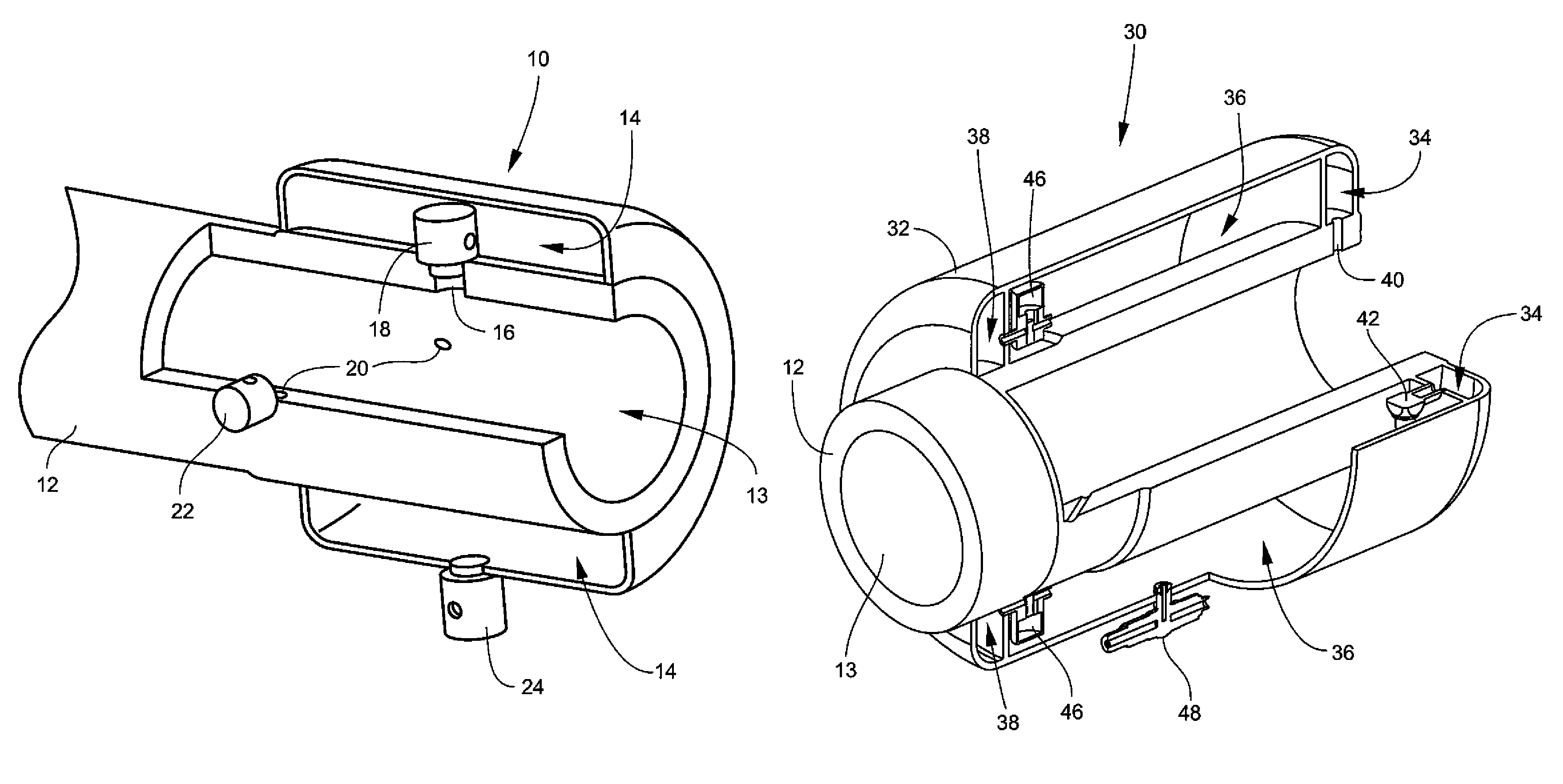
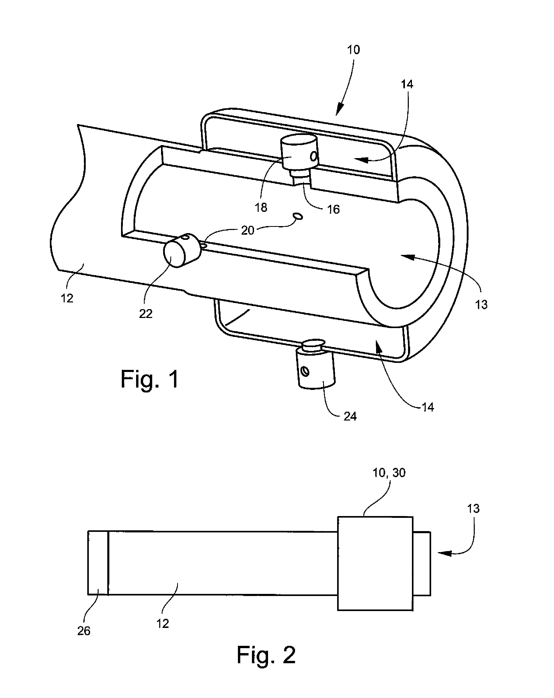
[0029]FIG. 1 is a partially cutaway, perspective view of one embodiment of a time-delayed bore evacuator 10 for a gun tube 12 having a bore 13. Bore evacuator 10 may include a reservoir 14. Reservoir 14 may be located anywhere along the length of gun tube 12. At least one intake port 16 may be provided between reservoir 14 and bore 13 of gun tube 12. A one-way valve 18 may be disposed in each intake port 16. One-way valve(s) 18 may allow gas flow only from bore 13 to reservoir 14. A plurality of intake ports 16 and respective valves 18 may be used. By way of example only, intake port 16 may have a diameter of about 10 mm.

[0030]At least one discharge port 20 may be provided between reservoir 14 and bore 13 of gun tube 12. Discharge port(s) 20 may be angled toward a muzzle end of gun tube 12. In that way, gas flow from port(s) 20 may entrain gas in bore 13 and may exit the muzzle end of the gun tube 12. A one-way time-delayed valve 22 may be disposed in each discharge port 20. One-way...


PUM


Abstract

A bore evacuator for a gun tube may include a time-delayed discharge valve. The time-delayed discharge valve may open substantially simultaneously with the opening of the breech of the gun tube. Gas discharged from the bore evacuator may evacuate the bore of the gun tube. The time delay of the time-delayed discharge valve may be activated by gas pressure in the bore evacuator. The bore evacuator may include a pressure-regulating valve for regulating the maximum pressure in the bore evacuator.

Description

STATEMENT OF GOVERNMENT INTEREST[0001]The inventions described herein may be manufactured, used and licensed by or for the U.S. Government for U.S. Government purposes.BACKGROUND OF THE INVENTION[0002]The invention relates in general to munitions and, in particular, to large caliber gun tubes, such as cannons.[0003]Bore evacuators may be used on large caliber cannons. Bore evacuators may be used to remove propellant gases from the gun bore of the cannon after firing. The gun may be attached to a vehicle that may be manned. The rear of the gun may include a breech. The breech may be located inside a crew compartment. Flash-back in the crew compartment may be a hazard. Exposure of the crew to toxic propellant gases may be a hazard.[0004]Some bore evacuator systems may use a reservoir to store high pressure propellant gases. Ports or nozzles may be located in the gun tube to charge and discharge the reservoir. The gun may include a means to quickly open the breech of the gun. The breec...

Claims


Application Information

Patent Timeline
Patent Type & Authority Patents(United States)
IPC IPC(8): F41A13/08
CPCF41A13/08
Inventor CLER, DANIEL L.
Owner UNITED STATES OF AMERICA THE AS REPRESENTED BY THE SEC OF THE ARMY
Why Eureka
Try Eureka