Rowing trainer

a trainer and rowing technology, applied in the field of rowing machines, can solve the problem of not accurately reproducing the “feel” of the rowing boat, and achieve the effect of reducing the energy expended in the movement of the athlete's body

Inactive Publication Date: 2010-11-16
BELL EDWARD J
View PDF120 Cites 12 Cited by
  • Summary
  • Abstract
  • Description
  • Claims
  • Application Information

AI Technical Summary

Benefits of technology

[0014]The rowing trainer thus described minimizes the amount of energy consumed during the rowing operation, insofar as the majority of the mass of the athlete's body does not move during the rowing stroke, due to the fact that the seat is stationary. The only component which exhibits translational motion relative to the frame is the rigger and oar assembly. The motion of the flywheel is rotational only; the flywheel does not translate relative to the frame.
[0018]The invention has the further object of providing a rowing trainer which minimizes the energy expended in moving the athlete's body.

Problems solved by technology

Although rowing machines of the prior art have generally used a sliding seat to accommodate the rowing motion, they do not accurately reproduce the “feel” of the boat.
Some of the rowing machines of the prior art do not simulate the motion of the oars about an oar lock, and therefore do not exercise the same muscles that would be used in actual rowing.

Method used


Image

  • Rowing trainer
  • Rowing trainer
  • Rowing trainer

Examples


Embodiment Construction

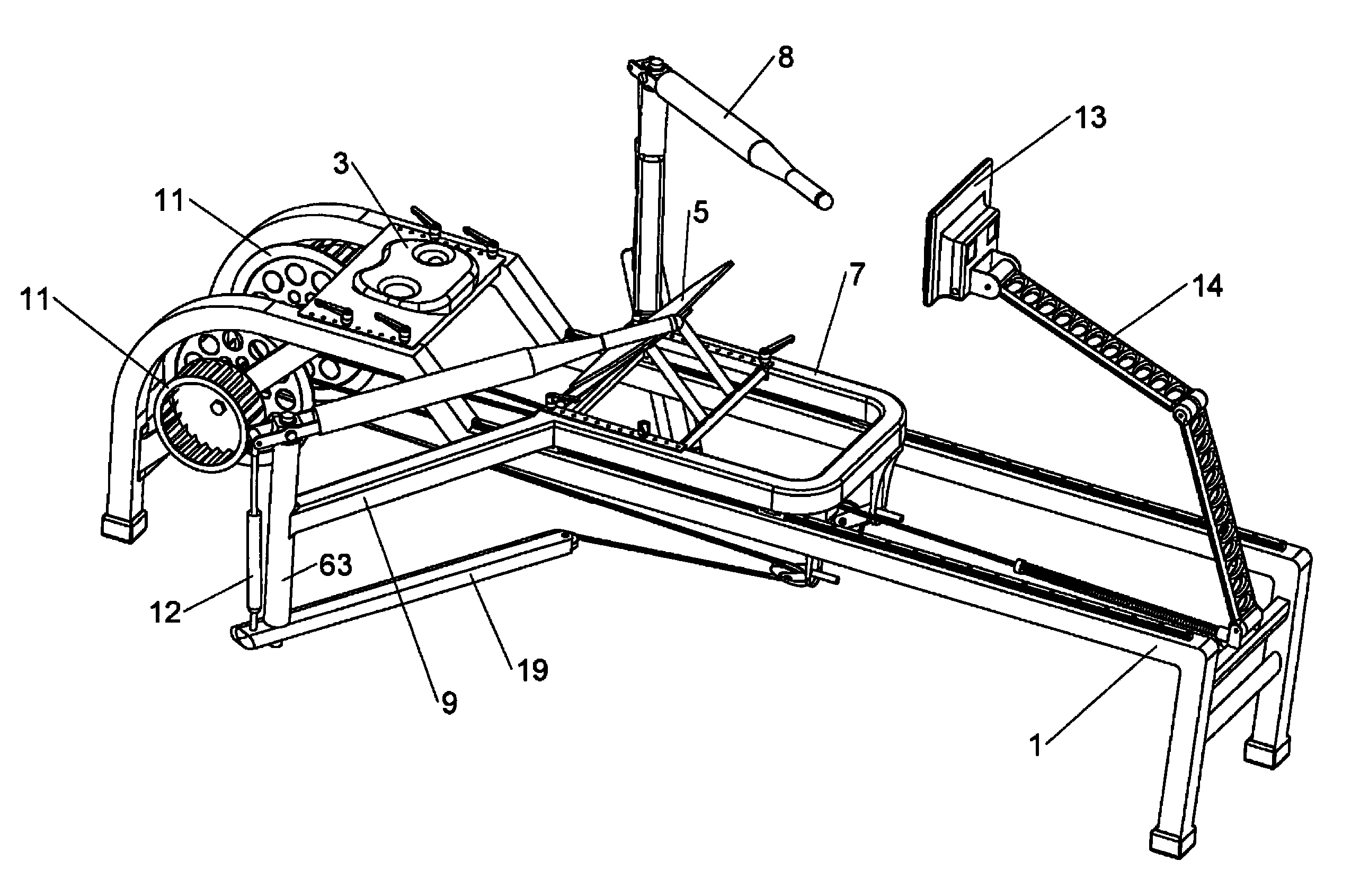
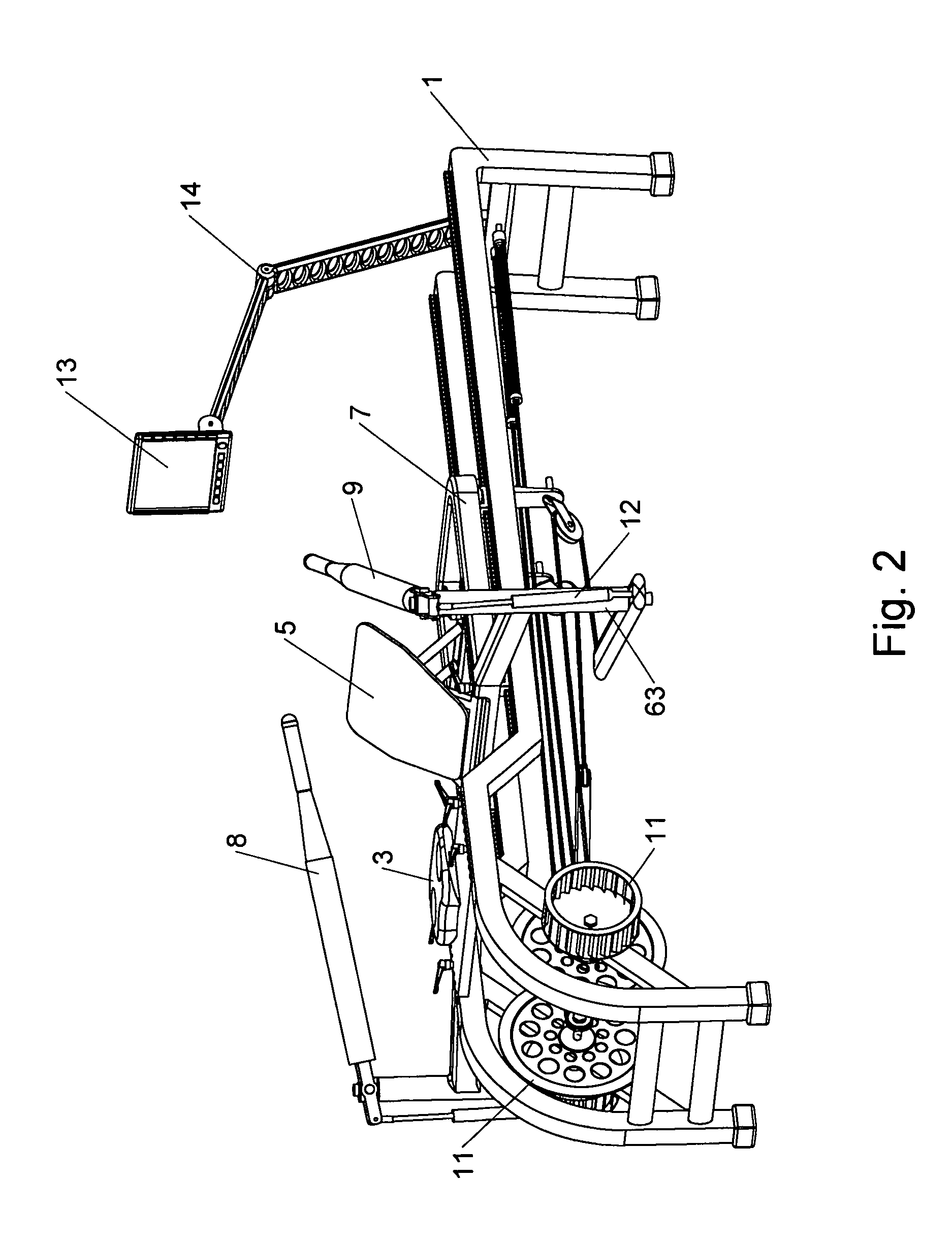
[0041]The present invention comprises a rowing trainer which simulates the actual experience of rowing a scull or boat.

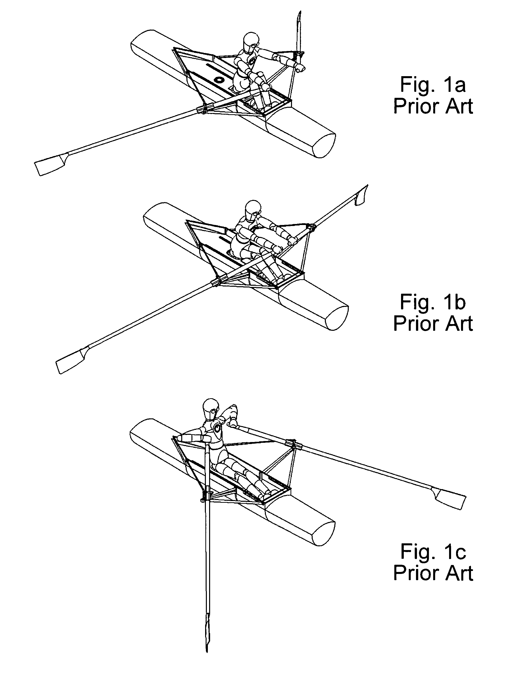
[0042]FIGS. 1a-1c illustrate the three major stages of a rowing stroke. These stages are labeled “catch”, “drive”, and “finish”, and apply both to the prior art and to the present invention. Reference will be made, later, to these stages, in describing the device of the present invention.

[0043]FIG. 1a shows a rower in a scull or boat, in the “catch” position. In this position, the athlete's legs are compressed, and the arms are extended. The oars are about to engage the water to perform the work of rowing.

[0044]FIG. 1b shows the rower in the “drive” position. The athlete's legs are nearly extended, and the arms are beginning to bend. This is the portion of the stroke which accomplishes most or all of the work of rowing, as the oars are moved through the water, with the oar blades oriented for maximum engagement with the water.

[0045]FIG. 1c shows the rower in the “fi...


PUM


Abstract

A rowing trainer includes a frame, and a seat affixed to the frame. A sliding rigger, which supports an oar assembly, is movable back and forth along the frame. The oars are indirectly connected to a cord which passes around at least one pulley, and which turns a flywheel. Neither the flywheel nor the seat translates relative to the frame. The only component which translates is the rigger and the associated oar assembly. The device closely simulates the experience of rowing an actual boat or scull.

Description

BACKGROUND OF THE INVENTION[0001]The present invention relates to the field of athletics training, and provides a rowing machine which closely simulates the feel of a scull or boat.[0002]Rowing machines have been known for many years. Examples of such machines are shown in U.S. Pat. Nos. 228,845, 381,187, 641,596, 1,504,375, 2,586,024, 3,572,700, 4,047,715, 4,396,188, 4,743,011, 4,846,460, 4,880,224, 4,884,800, 4,984,986, 5,013,033, 5,092,581, 5,295,931, 5,441,469, and 5,779,600. The disclosures of the above-cited patents are incorporated by reference herein.[0003]Rowing machines are used by the majority of rowing clubs and teams to improve fitness during inclement weather, as well as to supplement rowing training when there are a large number of athletes and insufficient coaches.[0004]A typical rowing machine of the prior art has a sliding seat which moves along the longitudinal axis of a simulated boat. In an actual racing scull or boat, the seat is movable along a pair of tracks,...

Claims


Application Information

Patent Timeline
Patent Type & Authority Patents(United States)
IPC IPC(8): A63B69/06A63B21/00
CPCA63B21/154A63B22/0076A63B21/225A63B2022/0079A63B2022/0084A63B2071/0647A63B2220/24A63B2220/34A63B2069/064
Inventor BELL, EDWARD J.
Owner BELL EDWARD J
Why Eureka
Try Eureka