Method and apparatus for dispensing a viscous material on a substrate

a technology of viscous material and substrate, which is applied in the direction of resistive material coating, liquid/fluent solid measurement, liquid transferring device, etc., can solve the problems of limited production rate of such dispensing systems, in some cases, and limited production rate of such systems

Active Publication Date: 2010-11-16
ILLINOIS TOOL WORKS INC
View PDF15 Cites 50 Cited by
  • Summary
  • Abstract
  • Description
  • Claims
  • Application Information

AI Technical Summary

Benefits of technology

[0015]Embodiments of the invention may further include calibrating a distance between first and second dispensing units and a camera. In one embodiment, steps (4) and (6) occur without contacting the electronic substrate. In a certain embodiment, steps (4) and (6) are achieved by using a non-contact-type dispensing unit configured to stream viscous material onto the electronic substrate. In another embodiment, steps (4) and (6) are achieved by using a non-contact-type dispensing unit configured to launch viscous material at a location on the electronic substrate. Steps (3) and (5) may be achieved by a gantry capable of moving a dispensing unit in X axis and Y axis directions, in which the gantry is incapable of moving the dispensing unit in a Z axis direction.

Problems solved by technology

The production rate of such dispensing systems, in some cases, may be limited by the rate at which a particular dispense pump assembly can accurately and controllably dispense dots or lines of material.
In other cases, the production rate of such systems may be limited by the rate at which parts can be loaded into and out of the machine.
In still other cases, the production rate of such systems may be limited by process requirements, such as the time required to heat a substrate to a particular temperature, or the time required for a dispensed material to flow, as in underfill applications.
In all cases and applications, there is some limit to the throughput capability of a single dispense system.
During the manufacture of integrated circuits, production requirements often exceed the throughput capabilities of a single dispensing system.

Method used


Image

  • Method and apparatus for dispensing a viscous material on a substrate
  • Method and apparatus for dispensing a viscous material on a substrate
  • Method and apparatus for dispensing a viscous material on a substrate

Examples


Embodiment Construction

[0020]For the purposes of illustration only, and not to limit the generality, the invention will now be described in detail with reference to the accompanying figures. This invention is not limited in its application to the details of construction and the arrangement of components set forth in the following description or illustrated in the drawings. The invention is capable of other embodiments and of being practiced or being carried out in various ways. Also the phraseology and terminology used herein is for the purpose of description and should not be regarded as limiting. The use of “including,”“comprising,”“having,”“containing,”“involving,” and variations thereof herein, is meant to encompass the items listed thereafter and equivalents thereof as well as additional items.

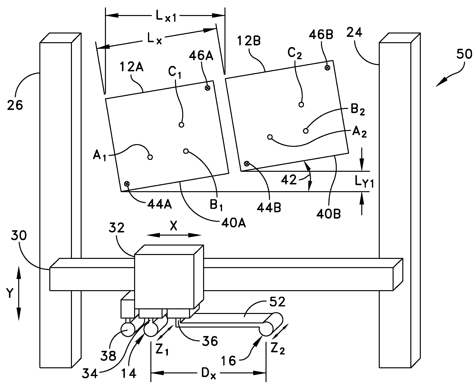
[0021]As mentioned above, in some cases, multiple independent dispensing systems are sometimes used to increase the production of dispense operations. This solution is often expensive, requiring multiple machin...


PUM

PropertyMeasurementUnit
viscousaaaaaaaaaa
distanceaaaaaaaaaa
dispensing heightaaaaaaaaaa

Abstract

A dispensing apparatus includes a frame, a support coupled to the frame to receive electronic substrates, a first dispensing unit to dispense viscous material, a second dispensing unit to dispense viscous material, and a gantry coupled to the frame. The gantry includes a first Z drive mechanism to support the first dispensing unit and lower the first dispensing unit toward a first electronic substrate pattern when performing a dispense operation, and a second Z drive mechanism to support the second dispensing unit and lower the second dispensing unit toward a second electronic substrate pattern when performing a dispense operation. The second Z drive mechanism may be adjusted relative to the first Z drive mechanism a predetermined distance. A controller controls a dispense operation of the first dispensing unit on the first electronic substrate pattern and a dispense operation of the second dispensing unit on the second electronic substrate pattern.

Description

BACKGROUND OF THE INVENTION[0001]1. Field of the Invention[0002]The invention relates generally to methods and apparatus for dispensing a viscous material on a substrate, such as a printed circuit board, and more particularly to a method and an apparatus for dispensing material on a substrate with enhanced efficiency.[0003]2. Discussion of Related Art[0004]There are several types of prior art dispensing systems used for dispensing precise amounts of liquid or paste for a variety of applications. One such application is the assembly of integrated circuit chips and other electronic components onto circuit board substrates. In this application, automated dispensing systems are used for dispensing dots of liquid epoxy or solder paste, or some other related material, onto circuit boards. Automated dispensing systems are also used for dispensing lines of underfill materials and encapsulents, which may be used to mechanically secure components to the circuit board. Exemplary dispensing sys...

Claims


Application Information

Patent Timeline
Patent Type & Authority Patents(United States)
IPC IPC(8): H01L21/00H05K13/04
CPCH01L21/6715H01L21/67023H05K13/0469B05C5/02B05C9/00H01L21/00H05K13/04
Inventor READ, HUGH R.
Owner ILLINOIS TOOL WORKS INC
Why Eureka
Try Eureka