Levitation magnetic actuator

a magnetic actuator and actuator technology, applied in the direction of armatures, coils, magnetic bodies, etc., can solve the problems of significant current consumption, low switching time, and poor quality of electric contact, so as to reduce the switching time and/or the actuating current zs

Inactive Publication Date: 2010-11-16
COMMISSARIAT A LENERGIE ATOMIQUE ET AUX ENERGIES ALTERNATIVES +3
View PDF10 Cites 3 Cited by
  • Summary
  • Abstract
  • Description
  • Claims
  • Application Information

AI Technical Summary

Benefits of technology

[0008]Another object of the invention is to provide a magnetic actuator with reduced current consumption during switching.
[0009]Another object of the invention is to provide a magnetic actuator with an improved and durable contact quality.
[0010]Another object of the invention is to provide a magnetic actuator, the mobile magnetic portion of which has increased angular stability.
[0012]Thus, by means of the part with reduced magnet weight, the mass of the mobile magnetic portion is reduced, the latter is switched more rapidly for a given actuating force or else a reduced actuating current is required for actuation for a given switching time. It is possible to act both on the switching time and on the actuating current.

Problems solved by technology

As compared with transistor switches, such magnetic levitation switches and generally mechanical contactors have a drawback which is that their switching time is not insignificant, it is of at least a few microseconds.
Another drawback exhibited by these actuators is that the quality of the electric contact may very well deteriorate after a large number of switchings.
Another drawback of these magnetic levitation switches is that they consume significant current upon switching.
This is not the case for transistors which when they are at rest, consume a little power and need to be continually supplied with power.

Method used


Image

  • Levitation magnetic actuator
  • Levitation magnetic actuator
  • Levitation magnetic actuator

Examples


Embodiment Construction

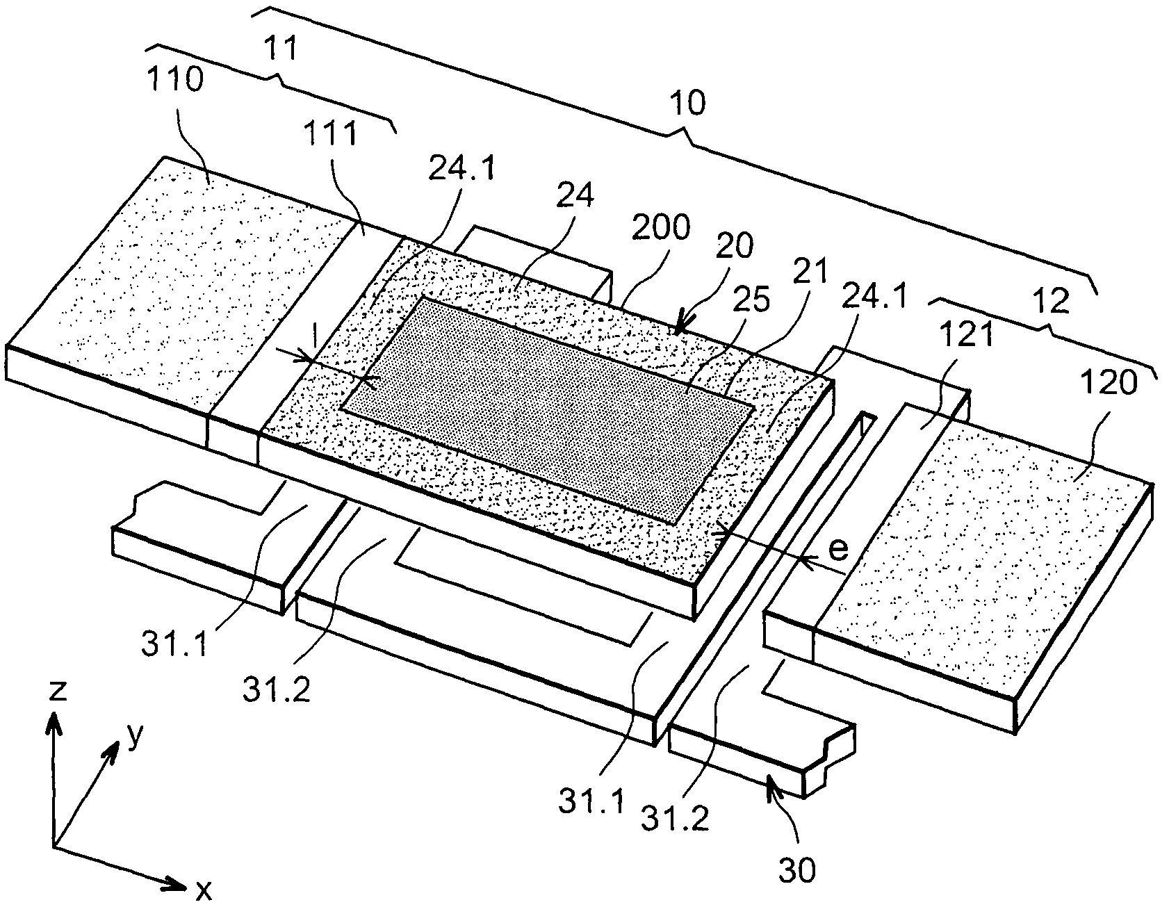
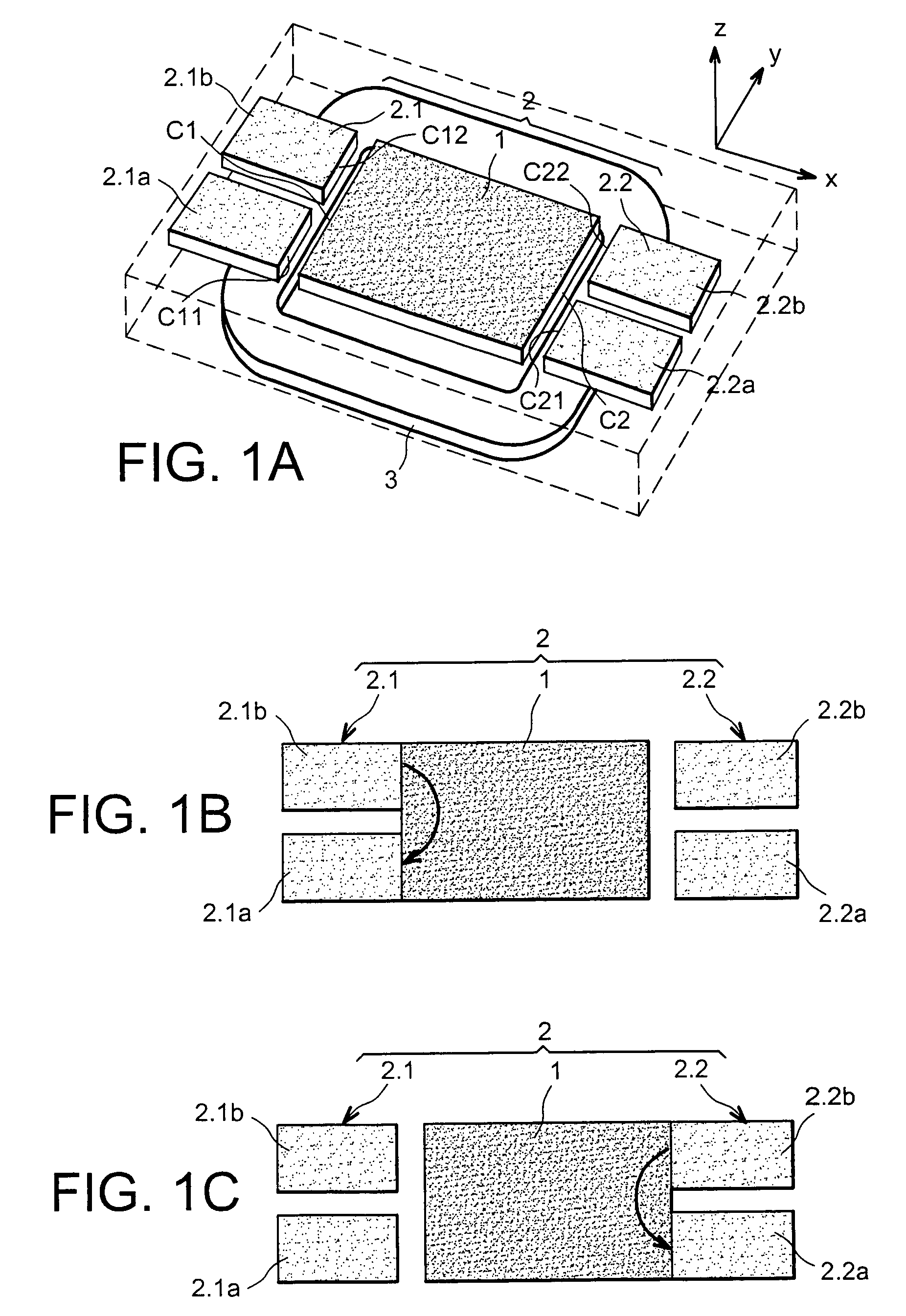
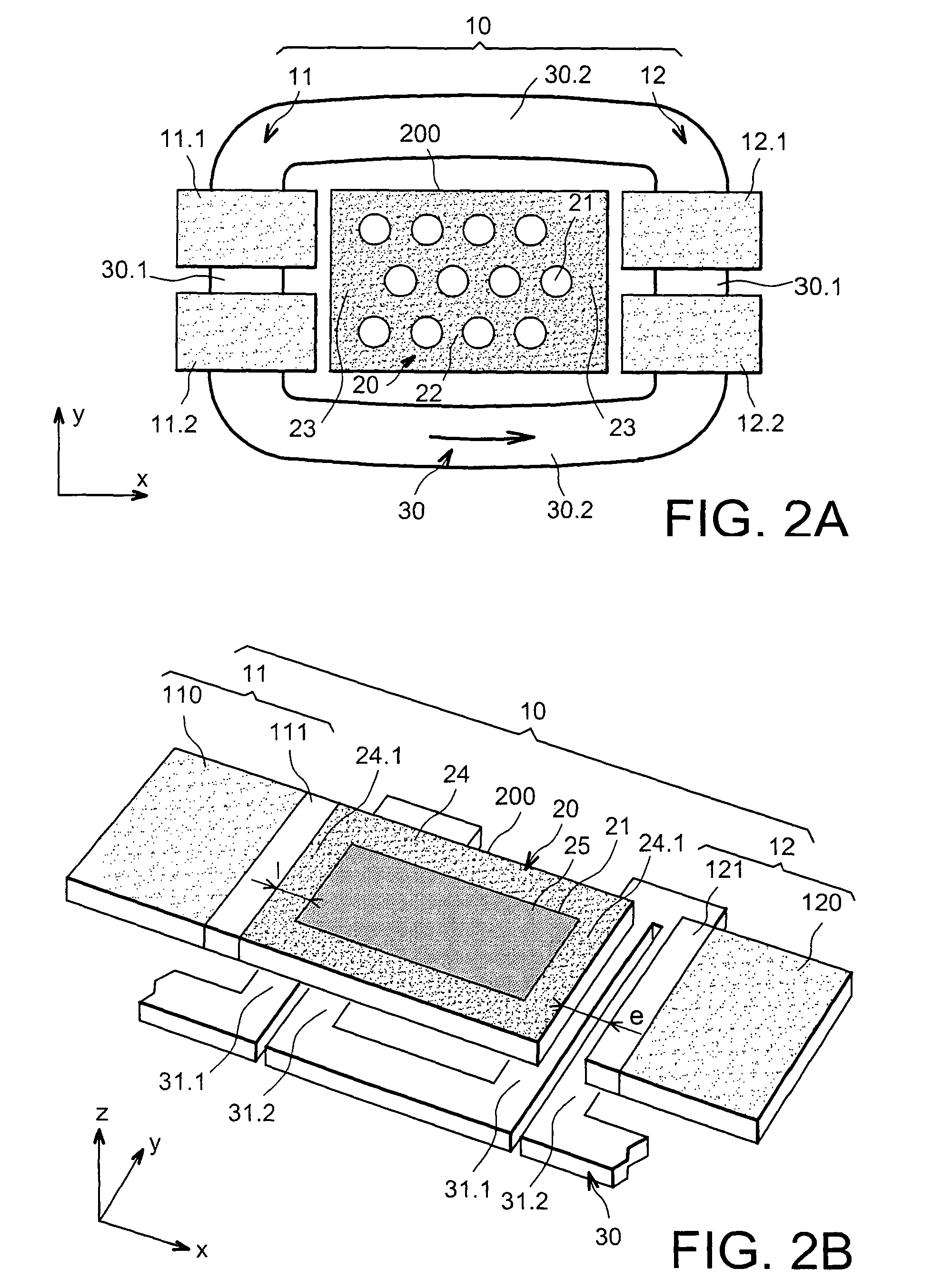
[0057]Reference is made to FIGS. 2A-2J which show different possible configurations for the mobile magnetic portion 20, the fixed magnetic portion 10 and the means 30 for triggering the displacement of the mobile magnetic portion 20 of a magnetic actuator according to the invention. This displacement is performed in a plane x, y, along the x axis.

[0058]The switching time of a magnetic for a given magnetic force applied on the mobile magnetic portion, is proportional to the mass of the mobile magnetic portion. In order that the mobile magnetic portion translationally moves between two attraction areas without being submitted to a side shift, its dimension in the direction of displacement should be large relatively to its two other dimensions. This is why the mobile magnetic portion generally is a rectangular magnet plate, the length of which is directed in the direction of the displacement. These considerations cause such a mobile magnetic portion to have a relatively significant vol...


PUM

PropertyMeasurementUnit
weightaaaaaaaaaa
massaaaaaaaaaa
displacementaaaaaaaaaa

Abstract

This is a magnetic actuator including a mobile magnetic portion (20), a fixed magnetic portion (10) provided with at least two attraction areas (11, 12) for the mobile magnetic portion (20), and means (30) for triggering the displacement of the mobile magnetic portion (20), the mobile magnetic portion (20) being in levitation when it is not in contact with an attraction area (11, 12). The mobile magnetic portion (20) includes a magnet-based part (200) with reduced magnet weight, this part (200) having an overall volume, and a mass which is less than the one it would have if its overall volume was totally occupied by the magnet.

Description

TECHNICAL FIELD[0001]The object of the present invention is a magnetic levitation actuator and notably a micro-actuator which may be made by microtechnology techniques.[0002]These magnetic actuators have a mobile magnetic portion and a fixed magnetic portion. The mobile magnetic portion is in levitation when it is not stuck to the fixed magnetic portion. Such actuators are very promising and in the future they may very well compete with transistor systems for performing switching.STATE OF THE PRIOR ART[0003]A magnetic actuator which includes as in FIGS. 1A, 1B, 1C, a mobile magnetic portion 1, a fixed magnetic portion 2, having at least two attraction areas 2.1, 2.2 for the mobile magnetic portion 1, and means 3 for triggering the displacement of the mobile magnetic portion 1, is known by French Patent application FR-A1-2,828,000 filed on Jul. 27, 2001 on behalf of the applicant. The mobile magnetic portion is formed with a magnet shaped as a rectangular plate. When it is not stuck ...

Claims


Application Information

Patent Timeline
Patent Type & Authority Patents(United States)
IPC IPC(8): H01F7/08
CPCH01F7/08
Inventor DELAMARE, JEROMECUGAT, ORPHEEDIEPPEDALE, CHRISTELMEUNIER-CARUS, JEROME
Owner COMMISSARIAT A LENERGIE ATOMIQUE ET AUX ENERGIES ALTERNATIVES
Why Eureka
Try Eureka