System and method for communicating over an 802.15.4 network

a communication system and network technology, applied in the field of data communication, to achieve the effect of simple setup and maintenance, low power, and flexibility of placemen

Inactive Publication Date: 2006-04-27
SIMPLE WORKS
View PDF23 Cites 42 Cited by
  • Summary
  • Abstract
  • Description
  • Claims
  • Application Information

AI Technical Summary

Benefits of technology

[0017] One of the objects of the present invention is to overcome the aforementioned problems and deficiencies. For example, an aspect of the present invention builds on digital imaging technologies using two newer pieces of technology. It combines the wireless IEEE 802.15.4 low power, low bandwidth protocol with CMOS imaging devices. In order to combine the imager solutions with an 8-bit HCO8 hardware architecture, the inventors propose storing one or more images in a temporary location, or buffer, so that it may be moved from end node to hub via the 802.15.4 architecture's transport limitations of 127 Bytes per packet. This buffer may exist on the Protocol Handler processor or on an adjunct flash component on the end node. The Transchip 5740 will allow up to 60K of storage on the Applications Processor; while other solutions will force the image through to the Protocol Handler on the End Node, where there is 32K or more of Flash storage space for temporary buffering of the image. Once the image is “stored” in the Applications Processor or in the Protocol Handler (within a flash memory for example), the 802.15.4 transport mechanism may move the picture in small “chunks”. This 802.15.4 transport architecture allows for 127 Bytes per packet. However, the effective payload is approximately 100 Bytes per packet, or per frame. Depending on the mode of operation of the 802.15.4 network (i.e., Beacon or Polling), the image stored in flash memory as, for example, 30K Bytes, can be either streamed or moved in 100 Byte “chunks” depending on acknowledgments and error correction within the algorithms. This is dependent on the inherent protocol handling of the 802.15.4 stack and logic of the network. Thus, an aspect of the present invention permits extraction of useful information (up to and including the entire file, although that is rarely necessary) in a timely manner from file sizes greater than an order of magnitude (i.e., ten times) greater than the 802.15.4 packet size transferred over an 802.15.4 network.
[0018] Thus, an aspect of the present invention takes advantage of a suite of technologies to enable the delivery of images over low-power RF networks using battery-powered cameras. Several advantages of these solutions are their integration into the 802.15.4 RF network, simplicity of setup and maintenance, flexibility of placement, and battery powered cameras. Due to their low current consumption and hibernation modes, the RF Networks' components can operate on battery power for long periods of time. The inventors have integrated digital CMOS imaging and the new, low-power IEEE 802.15.4 RF standard to create a “Plug and Play” remote wireless camera monitoring solution. Some “off the shelf” components may be used (such as the Transchip 5740 imager and the Freescale 802.15.4 ZigBee Transceiver (Evaluation Kit DIG528-2, part number 80000528000_R0203.DSN, Rev R02.03); however, the integration represents a novel concept. The integrated 802.15.4 cameras operate using flexible battery power and with the advantages of 802.15.4, should have long battery life. The inventors have added software to enable the solution to “plug and play” with up to 254 cameras controlled from 1 Coordinator, or Hub, plugged into the USB port of a personal computer. The USB port provides the power for the Coordinator. The 802.15.4 protocol enables us to communicate over ranges from a few meters to tens of meters, enabling a complete surveillance solution to cover a home or office complex. The range of the system can be extended substantially with the addition of a repeater.

Problems solved by technology

Due to their low current consumption and hibernation modes, the RF Networks' components can operate on battery power for long periods of time.

Method used


Image

  • System and method for communicating over an 802.15.4 network
  • System and method for communicating over an 802.15.4 network
  • System and method for communicating over an 802.15.4 network

Examples


Embodiment Construction

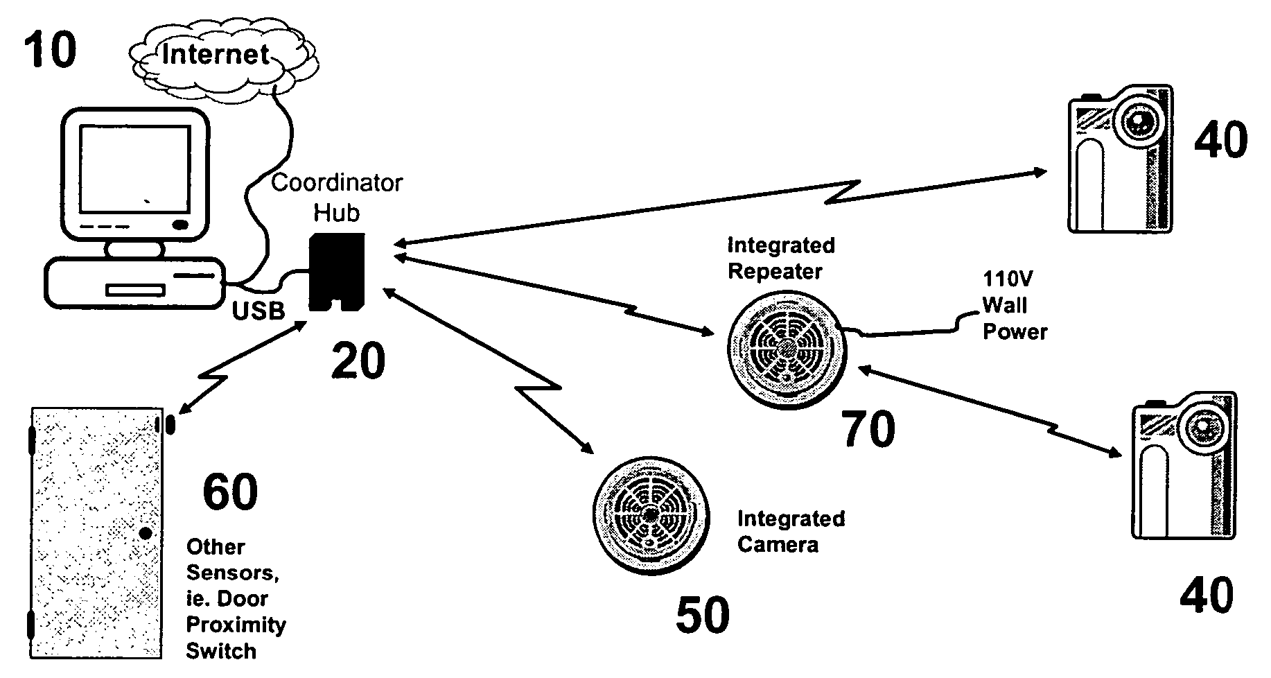
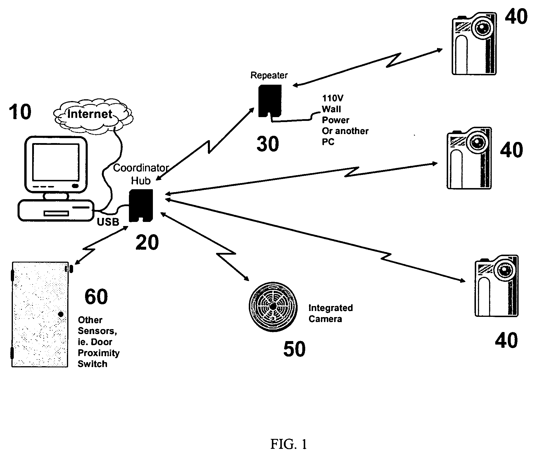
[0025]FIG. 1 depicts an exemplary embodiment of an 802.15.4 network according to the present invention. The basic system operates via the interaction of several components as shown in FIG. 1. In the basic setup, a computer 10 such as a personal computer (PC) with some control software requests an image from the system. The request could be for an image from one or multiple cameras within the network. The request may be based on a particular time period that has passed, or may be based on a triggering event (such as a door opening and triggering a sensor). The request is first directed to the Coordinator or Hub 20, which is attached to the computer via, perhaps, a USB connection. The Coordinator is built using an 802.15.4 Low Power RF Radio. The Hub 20 then communicates using a low-power RF protocol with the appropriate Repeaters 30 and Camera End Nodes 40 to acquire the image. The Repeaters may be fabricated using an 802.15.4 Low Power RF Radio. End Node Cameras may come in many for...


PUM


Abstract

A method of reducing data transfer while increasing image information over an 802.15.4 network includes obtaining an image with a sensor, modulating a representation of the image using a first 802.15.4 modem, sending the representation of the image to a coordinator, demodulating the representation of the image using a second 802.15.4 modem, and digitally enhancing at least one of the representation of the image and the image. A system for communication over an 802.15.4 network includes a sensor for obtaining data, the size of the data being at least an order of magnitude greater than the size of an 802.15.4 packet, a first 802.15.4 modem coupled to the sensor, a buffer for temporarily storing the data to allow transmission of portions of the data; the buffer being coupled to the sensor, a coordinator coupled to the sensor, the coordinator being capable of communicating with a computer, and a second 802.15.4 modem coupled to the coordinator.

Description

PRIORITY AND RELATED APPLICATION [0001] This application claims priority to U.S. patent application Ser. No. 60 / 612,901 filed Sep. 24, 2004 for “Remote Attendant,” the disclosure of which is hereby incorporated by reference in its entirety.FIELD OF THE INVENTION [0002] This application relates generally to data communication and particularly to data communication using the wireless IEEE 802.15.4 protocol over a WPAN (wireless personal area network) optimized for low power, low data rate networks. BACKGROUND INFORMATION [0003] The use of imaging technology is exploding with the advent of low-cost mega pixel digital cameras and cameras inside cell phones. Cities are routinely rolling out cameras in high-risk areas to help deter crime or provide background on events. Webcams, or cameras attached to a personal computer, continue to grow in popularity and free services are expanding to support their use, such as Yahoo! Messenger. Wireless home monitoring and control products are hitting ...

Claims


Application Information

Patent Timeline
Patent Type & Authority Applications(United States)
IPC IPC(8): H04Q7/24H04W28/14H04W84/12H04W84/18
CPCG01D21/00H04W28/14H04W84/12H04W84/18
Inventor BLACK, TOMMASON, DALESCHNEIDER, ROBERTBRICKETTO, PAUL
Owner SIMPLE WORKS
Why Eureka
Try Eureka