
Liquid crystal display device and method for driving the same

a liquid crystal display and display device technology, applied in clockwork cases, instruments, horology, etc., can solve the problems of deteriorating image brightness, ic chips that are driven by data drives, and ic chips that are aligned liquid crystal molecules, so as to shorten analog and digital power lines

Inactive Publication Date: 2010-11-16
LG DISPLAY CO LTD
View PDF5 Cites 2 Cited by
  • Summary
  • Abstract
  • Description
  • Claims
  • Application Information

AI Technical Summary

Benefits of technology

This solution maintains consistent driving voltages to pixel regions, preventing luminance differences and improving image quality by reducing voltage drops, especially in high-current scenarios.

Problems solved by technology

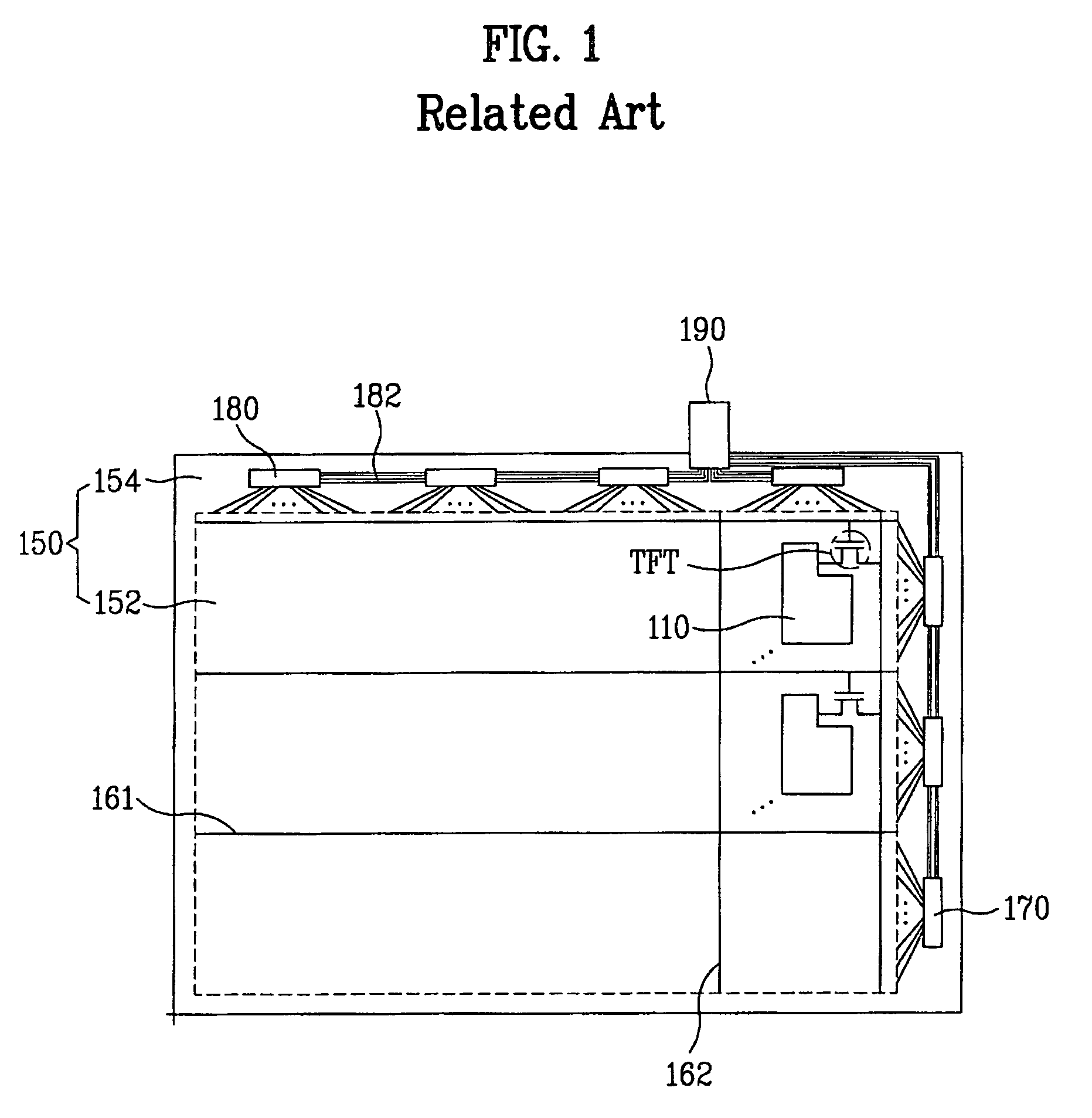
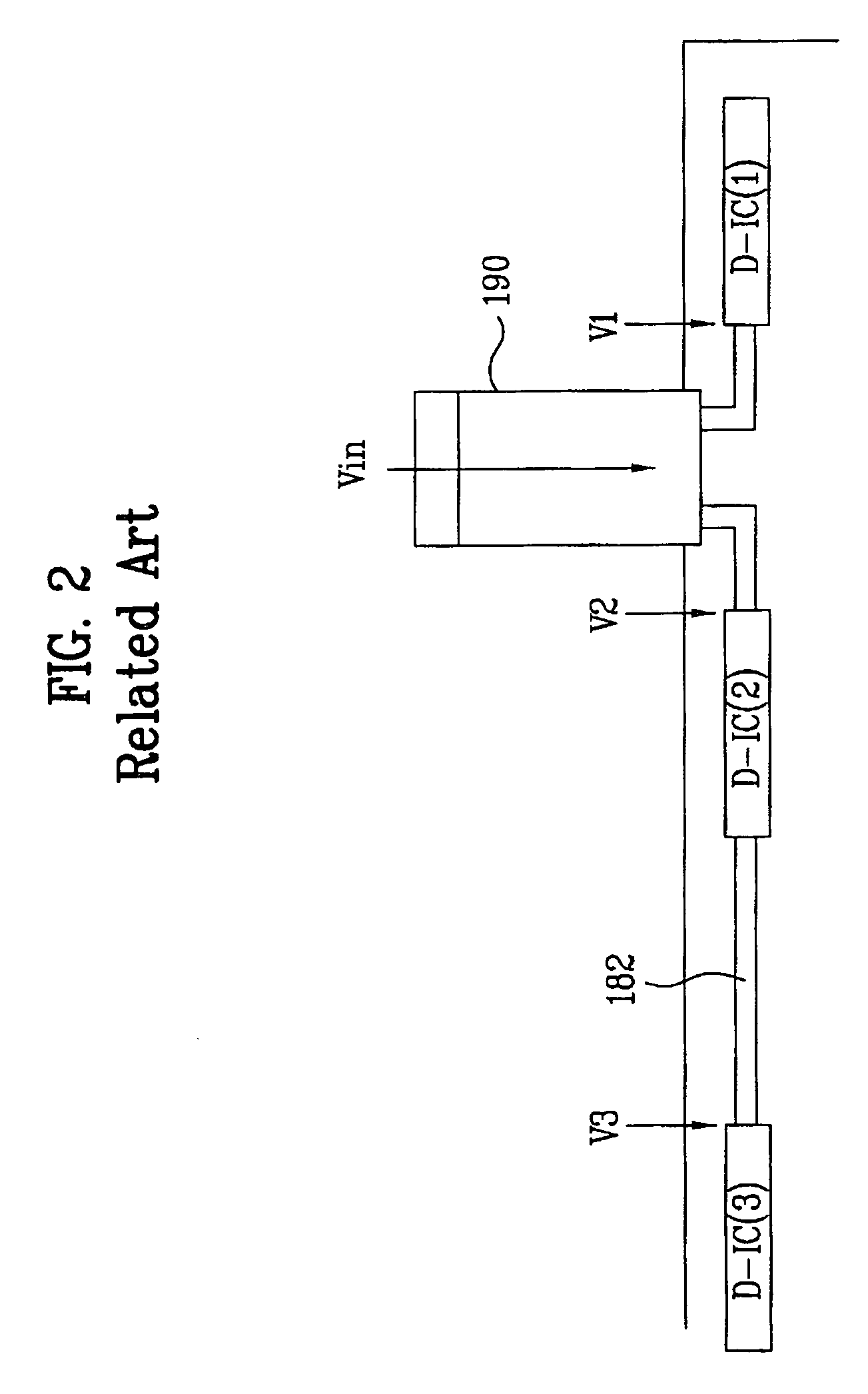
However, when the drive IC chips are cascaded, a problem occurs in that the driving voltage outputted from the data drive IC chips may drop.
As a result, it is difficult to align liquid crystal molecules to a desired direction, thereby deteriorating the brightness of the image.

Method used


Image

  • Liquid crystal display device and method for driving the same
  • Liquid crystal display device and method for driving the same
  • Liquid crystal display device and method for driving the same

Examples


Embodiment Construction

[0031]Reference will now be made in detail to the preferred embodiments of the present invention, examples of which are illustrated in the accompanying drawings. Wherever possible, the same reference numbers will be used throughout the drawings to refer to the same or like parts.

[0032]Hereinafter, a COG type LCD device according to one or more embodiments the present invention will be described with reference to the accompanying drawings.

[0033]FIGS. 3 and 4 are schematic views for explaining a driving line according to an embodiment of the present invention.

[0034]First, a COG type LCD device according to the embodiment of the present invention includes an image display area and a non-image display area.

[0035]The image display area includes a plurality of gate and data lines (not shown) crossing each other to define a plurality of pixel regions and a plurality of thin film transistors TFT corresponding to the pixel regions. Each TFT includes a gate electrode, a gate insulating layer,...


PUM

PropertyMeasurementUnit
driving voltage Vinaaaaaaaaaa

Abstract

A COG type LCD device and method are disclosed, which improve picture quality by minimizing driving voltage drop. The device according to an embodiment comprises an image area including a thin film transistor and a pixel electrode in a pixel region defined by gate and data lines crossing each other. A plurality of drive IC chips are formed using a COG (Chip On Glass) method in the periphery of the image display area. A LOG (Line On Glass) line is provided for cascading the plurality of drive IC chips to divide various signals inputted from an external driving circuit and to provide the divided signals to the respective drive IC chips. The LOG line includes analog and digital power lines. First and second switches are provided between the analog and digital power lines so as to temporarily short the analog and digital power lines.

Description

[0001]This application claims the benefit of the Korean Patent Application No. 10-2005-35629, filed on Apr. 28, 2005, which is hereby incorporated by reference as if fully set forth herein.BACKGROUND OF THE INVENTION[0002]1. Field of the Invention[0003]The present invention relates to a liquid crystal display (LCD) device, and more particularly, to a chip on glass (COG) liquid crystal display (LCD) device.[0004]2. Discussion of the Related Art[0005]Among the various flat display devices, liquid crystal display (LCD) devices have been widely used due to their advantageous characteristics such as high contrast ratio, good gray scale, good moving picture quality, and low power consumption.[0006]Generally, the LCD device includes a color filter CF array substrate having a color filter layer to represent colors, a thin film transistor TFT array substrate being disposed opposite to the CF array substrate, a liquid crystal layer formed between the TFT array substrate and the CF array subst...

Claims


Application Information

Patent Timeline
Patent Type & Authority Patents(United States)
IPC IPC(8): G09G3/36G02F1/1345
CPCG02F1/13452G02F1/1345G04B37/1426G04B37/0066
Inventor KIM, YOUNG OK
Owner LG DISPLAY CO LTD
Learn More