
Data transmission system for networks with non-full-duplex or asymmetric transport

a data transmission system and network technology, applied in the field of data transmission, can solve the problems of increasing latency, reducing data transmission efficiency, so as to minimize data transmission rate and optimize data transfer rate

Inactive Publication Date: 2015-04-30
SARATOGA DATA SYST
View PDF2 Cites 3 Cited by
  • Summary
  • Abstract
  • Description
  • Claims
  • Application Information

AI Technical Summary

Benefits of technology

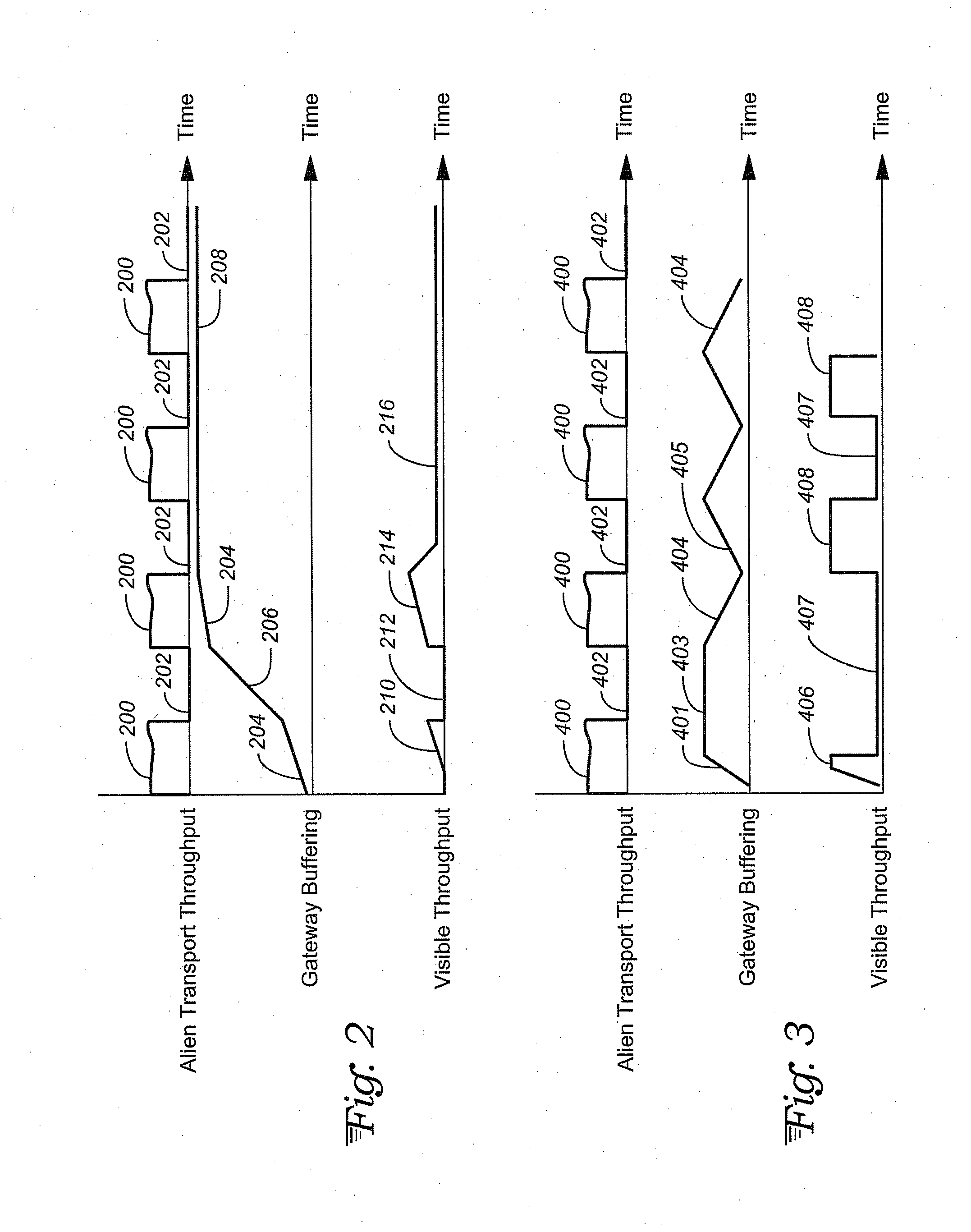
This patent describes a system for transferring data in a network with asymmetric transport characteristics. If the sender is aware of any non-full-duplex or asymmetric transport, they can send data to the gateway in chunks that match the transport's timing. The system also allows for a feedback channel to keep the gateway buffer full for peak throughput while minimizing data dropping. This method helps to optimize data transfer rates and ensures smooth data transfer between the sender and receiver.

Problems solved by technology

Many existing communications protocols like TCP / IP already suffer from transfer rate limitations due to network latency, traffic congestion and dropped datagrams or packets.
Even though the gateways that manage half duplex transport use buffers intended to maintain the illusion of full duplex communication for the sender and receiver, the existence of asymmetric transport tends to increase latency and worsen the problem of dropped datagrams or packets.
Too little loss (or corruption) implies that datagrams can be sent more frequently, while too much loss results in too much retransmission.
Overall, the effective throughput under such asymmetric transfer conditions is poor due to the predominance of so many datagram losses and the constant need for re-transmittal.

Method used


Image

  • Data transmission system for networks with non-full-duplex or asymmetric transport
  • Data transmission system for networks with non-full-duplex or asymmetric transport
  • Data transmission system for networks with non-full-duplex or asymmetric transport

Examples


Embodiment Construction

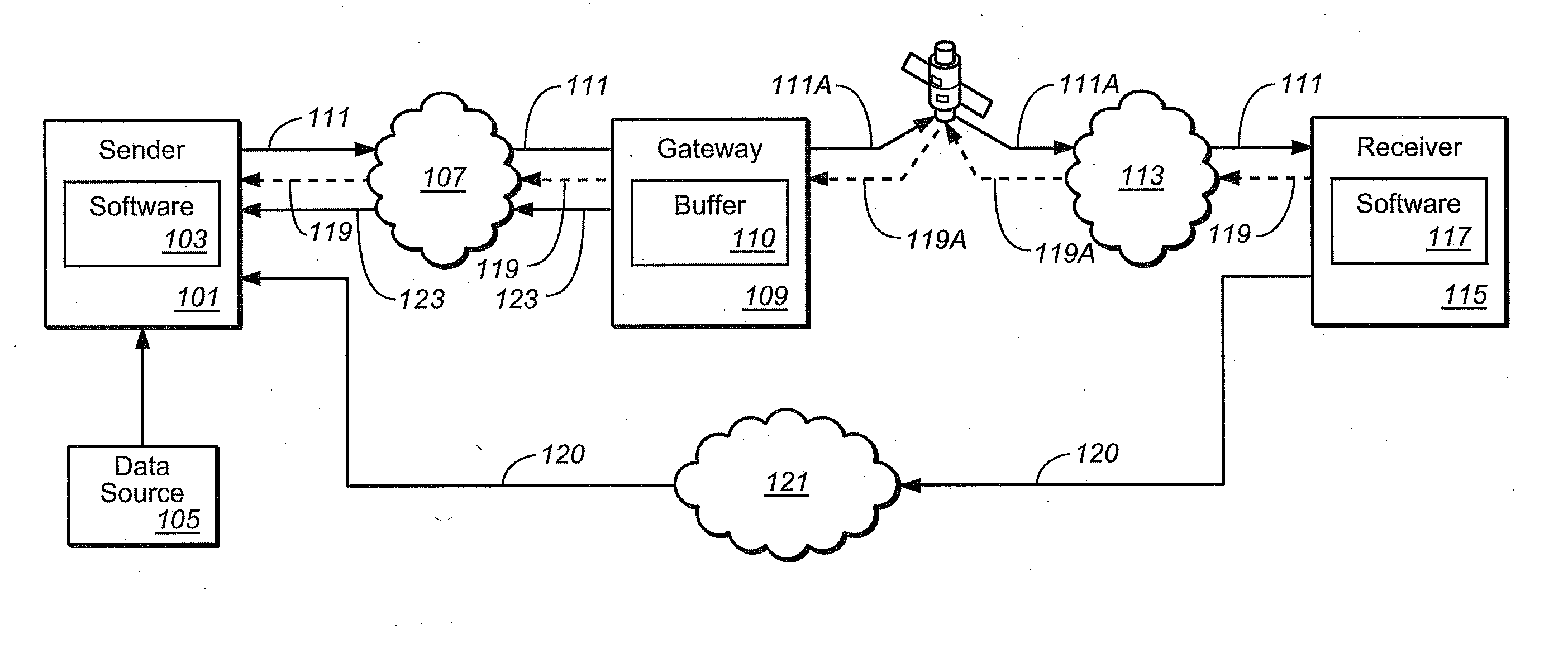
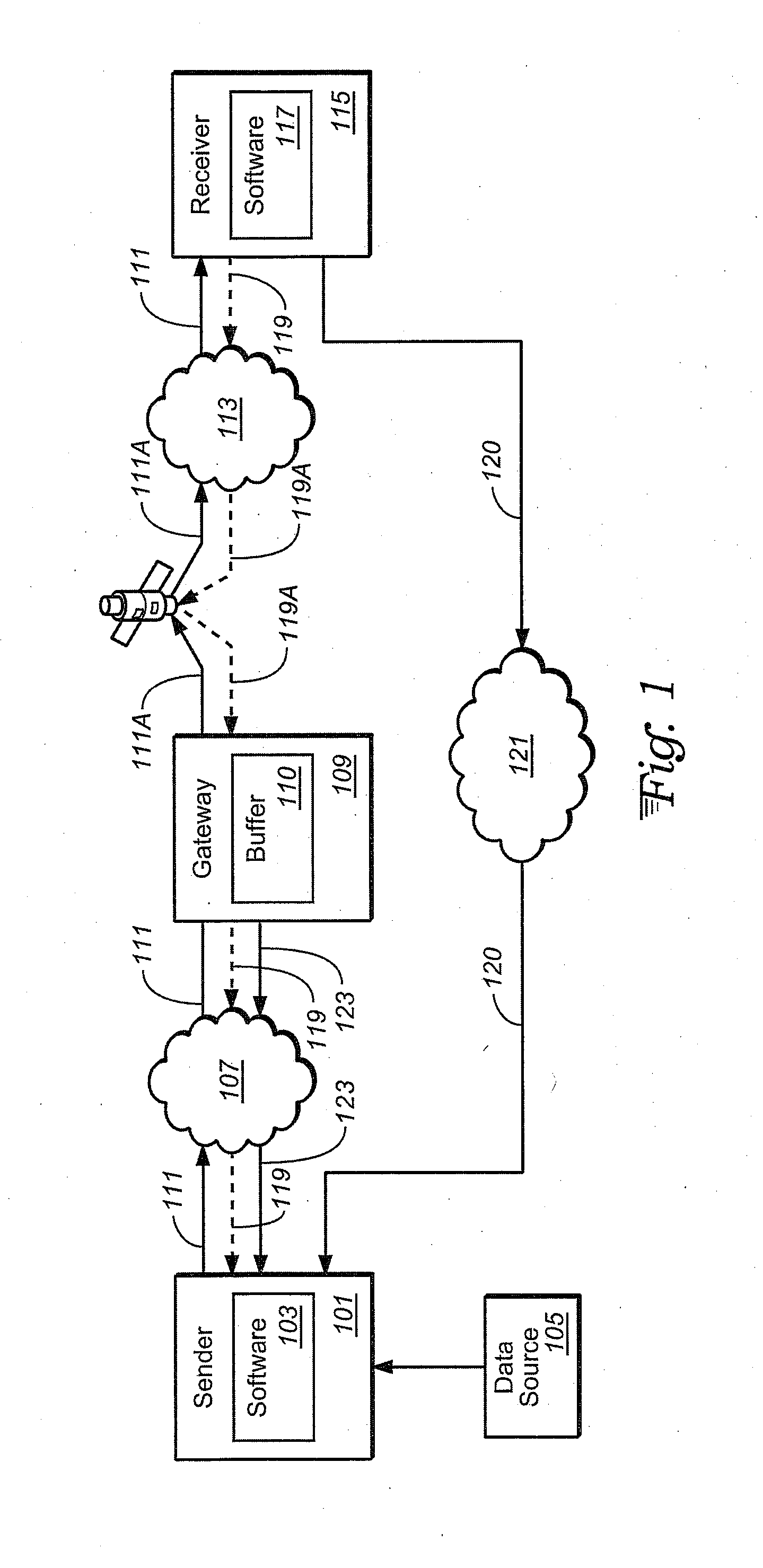
[0015]With reference to FIG. 1, a data transmission system couples a sender 101 to a receiver 115 for data transfer over a network 107, 113 and 121. Sender 101 and receiver 115 have software, 103 and 117 respectively, loaded on their computer hardware for implementing a data transfer protocol in accord with the present invention. The sender 101 has access to a data source 105 storing data that may be transferred over the network in response to a request from the receiver 115.

[0016]A data channel 111 is established between the sender 101 and receiver 115 over some available pathway 107, 113 of the network. The data channel 111 is seen here to include a portion 111A with asymmetric (e.g., non-full-duplex) characteristics, such as a radio or satellite link. Such asymmetric characteristics are alien to the full-duplex data transfer characteristics typically used in data networks via TCP / IP or similar protocols. This asymmetric portion 111A of the data channel 111 is mediated by a gatewa...


PUM


Abstract

A data transfer method and system are provided for networks having gateway-mediated asymmetric transport. Separate data and feedback channels are established between sender and receiver units, along with a gateway feedback channel between a gateway and the sender. The sender transmits datagrams to the gateway in temporal chunks corresponding to the asymmetric transport's timing to keep the gateway's buffer at an optimum fill for maximal throughput without transmit-end packet drops. The receiver acknowledges those datagrams that have been successfully received and identifies any missing or corrupt datagrams. At least some messages include timing information indicative of network latency and congestion. The sender resends datagrams identified as missing or corrupt. The sender self-tunes its transmission rate in reaction to changing network conditions, based upon gateway buffer fill, network latency and datagram loss rate to keep datagram loss rate below a specified upper bound.

Description

TECHNICAL FIELD[0001]The present invention relates to data transfers between sending and receiving devices in a networked environment, and in particular to such transfers where the underlying transport has non-full-duplex (e.g., half duplex) or other asymmetric characteristics.BACKGROUND ART[0002]Packet switched or network communications can be proxied through a gateway into an ‘alien’ transport, such as a half-duplex radio link or a high latency satellite connection, whereby the transport characteristics are modified away from the traditional full duplex communications commonly used for TCP / IP networks. Many existing communications protocols like TCP / IP already suffer from transfer rate limitations due to network latency, traffic congestion and dropped datagrams or packets. Even though the gateways that manage half duplex transport use buffers intended to maintain the illusion of full duplex communication for the sender and receiver, the existence of asymmetric transport tends to i...

Claims


Application Information

Patent Timeline
Patent Type & Authority Applications(United States)
IPC IPC(8): H04L12/863H04L12/819H04L12/26H04L47/21
CPCH04L47/621H04L47/21H04L43/0852H04L43/0829H04L47/263H04L47/28H04L47/30
Inventor COUSINS, ROBERT
Owner SARATOGA DATA SYST
Learn More