LED Driver with Auxiliary Power Output

a technology of led drivers and auxiliary power, which is applied in the direction of electroluminescent light sources, semiconductor lamp usage, electric lighting sources, etc., can solve the problems of reducing the efficiency of the converter, the power factor and thd of the input current will become degraded, and the difficulty of simultaneously having high coupling coefficients between multiple windings, etc., to minimize good thd and power factor, and the effect of reducing the drop in output voltag

Active Publication Date: 2017-01-19
EPTRONICS
View PDF5 Cites 1 Cited by
  • Summary
  • Abstract
  • Description
  • Claims
  • Application Information

AI Technical Summary

Benefits of technology

[0025]The present invention relates to power supplies for driving LEDs, and more particularly to primary side regulated switch mode power supplies configured to provide a substantial and varying auxiliary power supply for use by associated apparatus simultaneously with a regular output to an LED load.
[0026]A PSR flyback power supply for driving LEDs has a transformer with four windings; (1) for the primary power connected to the main flyback switch; (2) a feedback winding to supply VCC power for a control chip and to feedback to the control chip the loading conditions on the output (secondary) side of the transformer; (3) for the main secondary output power to drive the LED load; and (4) an auxiliary output winding to supply external power to associated circuitry. The coupling coefficient between auxiliary output winding 4 and feedback winding 2 is made to be higher than the coupling coefficient between feedback winding 2 and main secondary output power winding 3, although both coupling coefficients may be high.
[0027]This means that the control chip will be responsive to the loading of the auxiliary power winding, maintaining good THD and power factor as this loading varies. A consequence of this is that when the auxiliary power winding is loaded and its output voltage declines slightly, the control chip will order up more power to minimize the drop in output voltage. At the same time, the main output power winding 2 will receive more power and its voltage will rise slightly. The consequences of this are mitigated by placing the auxiliary power winding in series with the main output power winding so that the rise in voltage across the main output power winding will be compensated by the drop in voltage across the auxiliary power winding which is in series with it. Since it is conventional in these kinds of products to finally drive the LEDs from (for example) a constant current buck converter which draws its power from the main output power winding, then the current supplied to the LEDs remains constant even though the power being delivered by the auxiliary power winding may be varying considerably. The power factor and THD of the input current will remain within an acceptable range, for example THD less than 20% and power factor greater than 0.90.

Problems solved by technology

The extent to which this happens decreases the efficiency of the converter and is undesirable.
However, since the winding N4 is typically wound on the outside of a transformer with relatively loose coupling to the other windings, then when increasing amounts of power are drawn from it, this event is not fully reflected in the feedback signal sent back to the control chip from winding N2.
(It is difficult to simultaneously have high coupling coefficients between multiple windings at the same time, so a process of compromise is necessary.)
This means that the power factor and THD of the input current will become degraded when substantial power is drawn from the auxiliary power output since the control chip is not receiving a signal which properly reflects the power being drawn from that output.

Method used


Image

  • LED Driver with Auxiliary Power Output
  • LED Driver with Auxiliary Power Output
  • LED Driver with Auxiliary Power Output

Examples


Embodiment Construction

Glossary

[0073]PWM=pulse width modulation[0074]Mps=mutual inductance between primary and secondary windings[0075]PSR=primary side regulated[0076]AC=alternating current[0077]FET=field effect transistor[0078]LED=light emitting diode[0079]VCC=voltage common power supply[0080]THD=total harmonic distortion[0081]EE transformer=transformer using cores shaped like the letter E[0082]EI transformers=transformer using one E shaped core (E core) and one straight line core (I[0083]core)[0084]JFET=junction gate field-effect transistor[0085]IGBT=insulated-gate bipolar transistor[0086]AC / DC power converter=alternating current to direct current power converter

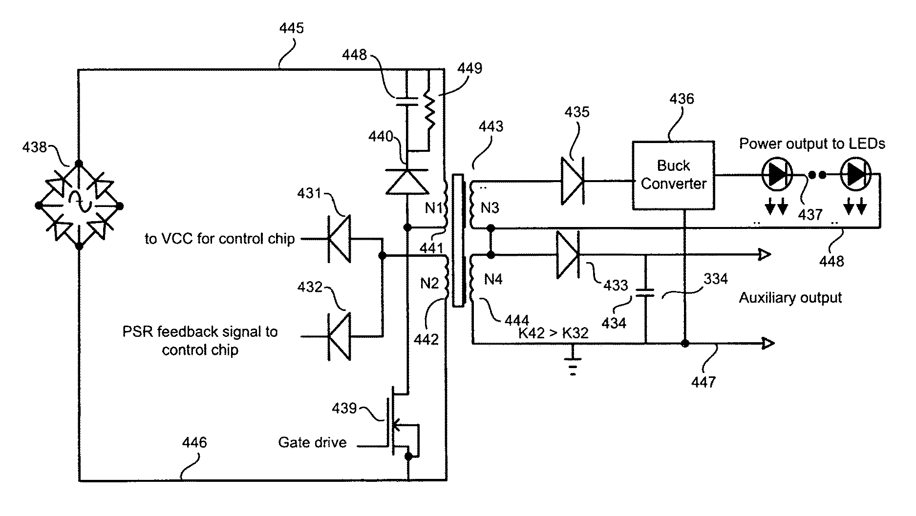
[0087]The operation of the preferred embodiment is shown in FIG. 4, which relates to prior art FIG. 3 in that corresponding parts have a call out number which begins with the digit 4 instead of the digit 3. In most respects this circuit resembles a conventional primary side regulated (PSR) flyback, but with critical differences which will be exp...


PUM


Abstract

An LED driver has a primary side regulation with at least one input connected to the AC power line, and at least two outputs. At least one output is for driving LEDs and at least one output is for providing auxiliary power for associated circuits. The driver is constructed using the flyback principle, having at least one flyback transformer which has at least one primary winding connected to a flyback switching transistor. At least one principal output winding is connected to the LED load, and at least one feedback winding is connected to a control chip. At least one auxiliary winding drives the auxiliary power output. The auxiliary winding has a coupling coefficient to said feedback winding which is greater than the coupling coefficient between the principal output winding and the feedback winding.

Description

TECHNICAL FIELD[0001]The present invention is in the field of primary side regulated LED drivers having an auxiliary power output.BACKGROUND OF THE INVENTION[0002]Flyback converters for driving LED arrays from the AC power line are well known in the art. See for example, Fairchild Semiconductor publication application note AN-9750, entitled High-Power Factor Flyback Converter for LED Driver with FL7732 PSR Controller, the disclosure of which is incorporated herein by reference, which shows a flyback controller. One of the features which is conventional in a flyback transformer design is to have close coupling between the primary winding and the secondary or output winding. This is because if there is flux leakage, as illustrated in FIG. 1, then when the primary switch is opened, energy stored in the leakage flux field must be dissipated somehow, usually as heat in a snubber arrangement. The extent to which this happens decreases the efficiency of the converter and is undesirable. Th...

Claims


Application Information

Patent Timeline
Patent Type & Authority Applications(United States)
IPC IPC(8): H05B33/08H05B44/00
CPCH05B33/0815Y02B20/30H05B45/385H05B45/375H05B45/10H05B47/10H05B45/382
Inventor O'NEIL, TOMCHIANG, LEE
Owner EPTRONICS
Why Eureka
Try Eureka