Anti-fretting wear spacer grid with canoe-shaped spring

a canoe-shaped spring and wear-resistant technology, applied in the field of spacer grids, can solve the problems of damage to the fuel rod, vibration of the fuel rod, and inability to resist the vibration of the fuel rod, and achieve the effect of reducing the fretting wear depth and diminishing the partial abrasion of the fuel rod

Active Publication Date: 2010-11-16
KEPCO NUCLEAR FUEL CO LTD
View PDF10 Cites 5 Cited by
  • Summary
  • Abstract
  • Description
  • Claims
  • Application Information

AI Technical Summary

Benefits of technology

[0021]Accordingly, the present invention has been made in view of the above-mentioned problems occurring in the prior art, and it is an object of the present invention to provide an anti-fretting wear spacer grid with canoe-shaped springs that can provide the linear contact with a fuel rod such that the linear contact is extended as long as possible from initial contact to final contact, thereby achieving greater reduction of the fretting wear depth when compared with the same fretting wear area.
[0022]It is another object of the present invention to provide an anti-fretting wear spacer grid with canoe-shaped springs wherein the shape of the contact surface between the canoe-shaped springs and a fuel rod can be constantly maintained through the entire manufacturing procedure of the fuel rod in the nuclear reactor.
[0024]According to the present invention, therefore, there is provided an anti-fretting wear spacer grid with canoe-shaped springs that can provide the linear contact with a fuel rod such that the linear contact is extended as long as possible from initial contact to final contact, thereby achieving greater reduction of the fretting wear depth when compared with the same fretting wear area.
[0025]Additionally, there is provided an anti-fretting wear spacer grid with canoe-shaped springs wherein the shape of the contact surface between the canoe-shaped springs and a fuel rod can be constantly maintained through the entire manufacturing procedure of the fuel rod in the nuclear reactor, thereby diminishing the partial abrasion of the fuel rod due to irregular contact.

Problems solved by technology

However, the above-mentioned methods of enhancing the thermal transmission efficiencies of nuclear fuel assemblies also generate turbulences in coolant flowing around the fuel rods, and the turbulences of the coolant undesirably cause flow-induced vibration by which the fuel rods are vibrated.
The flow-induced vibration of the fuel rods 1 causes the fuel rods to slide against their contact surfaces at which the fuel rods are brought into contact with the springs and dimples of the spacer grids, such that the contact surfaces are partially abraded to cause fretting wear of fuel rods to occur, which results in the damage on the fuel rods.
That is, the above-mentioned methods for improving the thermal performance so as to develop the high burn-up fuel result in the acceleration of the damage of the fuel rods.
Also, the fuel rods are repeatedly contracted by the radial creeps in the burn-up process in the reactor, that is, by the high pressure caused by the coolant in the reactor, and extended radially by the expansion of fuel pellets, such that the outer diameters of the fuel rods have irregular directionality, which generates the gap between the springs / dimples of the spacer grid and the fuel rod, thereby causing much fretting wear.
Further, in case where the contact portion of the spring does not have a theoretically complete curved surface, the irregular linear or point contact of the spring 62 with the fuel rod 1 is formed to cause unexpected fretting wear to happen.

Method used


Image

  • Anti-fretting wear spacer grid with canoe-shaped spring
  • Anti-fretting wear spacer grid with canoe-shaped spring
  • Anti-fretting wear spacer grid with canoe-shaped spring

Examples


Embodiment Construction

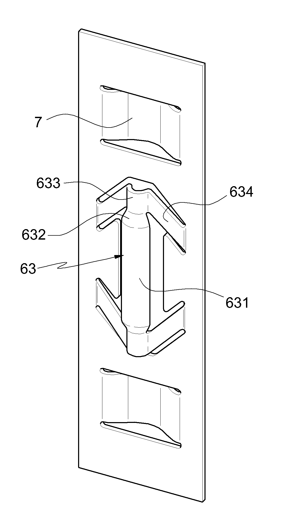
[0039]Hereinafter, an explanation on an anti-fretting wear spacer grid with canoe-shaped springs according to the present invention will be given with reference to the attached drawings. In the following description, wherever possible, the same reference numerals will be used throughout the drawings and the description to refer to the same or like parts.

[0040]On the other hand, the individual space portion defined by the lattice structure of the spacer grid is called a grid cell, and one surface of the interior of the grid cell is called one grid cell surface. Also, if one grid cell surface is disposed in a longitudinal direction, all of the grid cell surfaces located parallel thereto become the grid cell surface being in the longitudinal direction, and the grid cell surfaces located perpendicular to the grid cell surface being in the longitudinal direction becomes those being in the transverse direction. Further, an axial direction is a length direction of the unit grid cell, to wh...


PUM


Abstract

The present invention relates to an anti-fretting wear spacer grid having a plurality of canoe-shaped springs formed thereon, wherein each of the canoe-shaped springs includes: a fuel rod-contacting part having a flat surface having a predetermined longitudinal length so as to have linear contact with the fuel rod; a curved face-connecting part formed on the upper and lower portions of the fuel rod-contacting part; a leg-connecting part formed on the end portion of the curved face-connecting part; and legs each being formed of a plate shape having a predetermined length and connecting the both sides of the leg-connecting part with one unit grid cell surface.

Description

[0001]This is a non-provisional application under 35 U.S.C. §1.111(a) which claims priority from Korean patent application 10-2007-0086024 filed on Aug. 27, 2007, which is incorporated herein by reference.BACKGROUND OF THE INVENTION[0002]1. Field of the Invention[0003]The present invention relates to a spacer grid used for placing and supporting a plurality of nuclear fuel rods within a nuclear fuel assembly, and more particularly, to an anti-fretting wear spacer grid with canoe-shaped springs capable of preventing the fretting wear of fuel rods, thereby avoiding the damage of the fuel rods.[0004]2. Background of the Related Art[0005]A nuclear reactor is a device that artificially controls the chain reaction of the nuclear fission of fissile materials, thereby achieving a variety of use purposes such as the generation of heat, the production of radioisotopes and plutonium, the formation of radiation fields, or the like.[0006]Generally, enriched uranium that is obtained by raising a ...

Claims


Application Information

Patent Timeline
Patent Type & Authority Patents(United States)
IPC IPC(8): G21C3/34
CPCG21C3/352G21C3/3563Y02E30/40Y02E30/30G21C3/356G21C3/34
Inventor EOM, KYONG-BOKIM, KYU-TAESUH, JUNG-MINLEE, SHIN-HOPARK, NAM-GYUPARK, JOON-KYOOKIM, JIN-SUNKIM, IL-KYULEE, SEONG-KICHOI, JOON-HYUNG
Owner KEPCO NUCLEAR FUEL CO LTD
Why Eureka
Try Eureka