Gas damper and bearing in a propulsion system

a technology of propulsion system and gas damper, which is applied in the direction of machines/engines, climate sustainability, sustainable transportation, etc., can solve the problems of direct contact between components that can require higher actuation forces at the joints, excessive wear, fretting wear,

Active Publication Date: 2021-08-17
RTX CORP
View PDF13 Cites 1 Cited by
  • Summary
  • Abstract
  • Description
  • Claims
  • Application Information

AI Technical Summary

Benefits of technology

[0003]According to one embodiment, a component assembly of a propulsion system includes a component housing having a plenum configured to receive a pressurized gas flow of the propulsion system. The component assembly also includes a lug integrally formed with the component housing, a lug base region including a vent hole forming a gas path between the plenum and an interior of the lug, and a pin. The pin is configured to be positioned within the interior of the lug, where a cavity is formed between an interior surface of the lug and an exterior surface of the pin as positioned within the lug, thereby forming a compressed gas layer to reduce vibration of the pin within the cavity based on the pressurized gas flow passing from the plenum through the vent hole into the cavity.
[0004]In addition to one or more of the features described above or below, or as an alternative, further embodiments may include a journal cutout within the interior of the lug and proximate to the vent hole, where the journal cutout is configured to reduce premature expulsion of the pressurized gas flow to an environment external to the component assembly.
[0006]In addition to one or more of the features described above or below, or as an alternative, further embodiments may include where damping of a plurality of vibratory loads is provided as the pin compresses the pressurized gas flow between the vent hole and an environment external to the component assembly, thereby reducing fretting wear of the component assembly.
[0010]According to an embodiment, a gas turbine engine of a propulsion system includes a fan section, a compressor section, a combustor section, a turbine section, and a nozzle. The gas turbine engine also includes a component assembly of the fan section, the compressor section, the combustor section, the turbine section, or the nozzle. The component assembly includes a component housing having a plenum configured to receive a pressurized gas flow of the gas turbine engine, a lug integrally formed with the component housing, a lug base region comprising a vent hole forming a gas path between the plenum and an interior of the lug, and a pin. The pin is configured to be positioned within the interior of the lug, where a cavity is formed between an interior surface of the lug and an exterior surface of the pin as positioned within the lug, thereby forming a compressed gas layer to reduce vibration of the pin within the cavity based on the pressurized gas flow passing from the plenum through the vent hole into the cavity.
[0013]According to an embodiment, a method includes providing a pressurized gas flow in a plenum of a component assembly of a propulsion system and directing the pressurized gas flow from the plenum through a vent hole to a lug of the component assembly. The pressurized gas flow circulates in a cavity between an interior surface of the lug and an exterior surface of a pin positioned within the lug, thereby forming a compressed gas layer to reduce vibration of the pin within the cavity. The pressurized gas flow is released from the cavity to an environment external to the component assembly.
[0014]In addition to one or more of the features described above or below, or as an alternative, further embodiments may include damping a plurality of vibratory loads as the pin compresses the pressurized gas flow between the vent hole and the environment external to the component assembly, thereby reducing fretting wear of the component assembly.

Problems solved by technology

Excessive gaps in mechanical joints can result in excessive wear.
For example, larger gaps between components that are subject to relative motion can experience vibratory loads that result in fretting wear.
Further, direct contact between components can require higher actuation forces at the joints.
A mechanical bushing or bearing may be used in some locations to alleviate rotational issues at joints; however, mechanical bushings and bearings add weight and complexity to mechanical systems.

Method used


Image

  • Gas damper and bearing in a propulsion system
  • Gas damper and bearing in a propulsion system
  • Gas damper and bearing in a propulsion system

Examples


Embodiment Construction

[0029]A detailed description of one or more embodiments of the disclosed apparatus and method are presented herein by way of exemplification and not limitation with reference to the Figures.

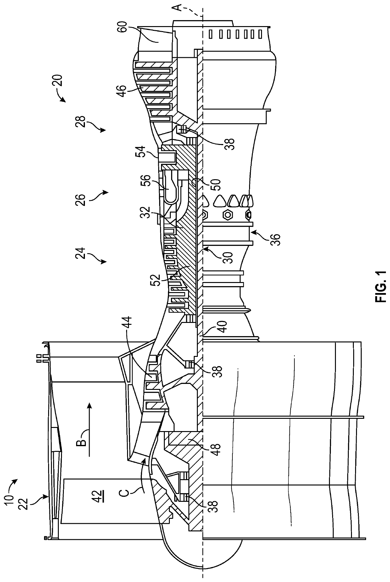
[0030]FIG. 1 schematically illustrates a gas turbine engine 20 as part of a propulsion system 10 that can include multiple instances of the gas turbine engine 20 and other components (not depicted). The gas turbine engine 20 is disclosed herein as a two-spool turbofan that generally incorporates a fan section 22, a compressor section 24, a combustor section 26 and a turbine section 28. The fan section 22 drives air along a bypass flow path B in a bypass duct, while the compressor section 24 drives air along a core flow path C for compression and communication into the combustor section 26 then expansion through the turbine section 28. Although depicted as a two-spool turbofan gas turbine engine in the disclosed non-limiting embodiment, it should be understood that the concepts described herein ar...


PUM


Abstract

A component assembly of a propulsion system includes a component housing having a plenum configured to receive a pressurized gas flow of the propulsion system. The component assembly also includes a lug integrally formed with the component housing, a lug base region including a vent hole forming a gas path between the plenum and an interior of the lug, and a pin. The pin is configured to be positioned within the interior of the lug, where a cavity is formed between an interior surface of the lug and an exterior surface of the pin as positioned within the lug, thereby forming a compressed gas layer to reduce vibration of the pin within the cavity based on the pressurized gas flow passing from the plenum through the vent hole into the cavity.

Description

BACKGROUND[0001]The subject matter disclosed herein generally relates to propulsion systems and, more particularly, to a method and an apparatus for providing a gas damper and bearing in a propulsion system.[0002]A propulsion system for an aircraft can include one or more gas turbine engines that combust fuel and provide propulsive power. Gas turbine engines include mechanical components that may be linked at joints by hinge pins. Components within a gas turbine engine may be subjected to extreme temperature variations depending on operating environment and relative position upstream or downstream from the combustor section. Mechanical joints may include gap space to account for thermal growth and other considerations, e.g., manufacturing tolerances. Excessive gaps in mechanical joints can result in excessive wear. For example, larger gaps between components that are subject to relative motion can experience vibratory loads that result in fretting wear. Wear can also occur in joints...

Claims


Application Information

Patent Timeline
Patent Type & Authority Patents(United States)
IPC IPC(8): F01D25/04
CPCF01D25/04F05D2220/323F05D2260/20F05D2260/96F02K1/12F02K1/80F02K1/822F05D2240/53F05D2240/54F05D2260/50Y02T50/60
Inventor MOUSTAKAKIS, MICHAEL P.BOWERS, DANIEL R.
Owner RTX CORP
Why Eureka
Try Eureka