Radially displaceable brush seal

a brush seal and radial dislocation technology, applied in the field of fluid seals, can solve the problems of affecting the life of the brush seal, causing the occurrence of metal contact at the sliding interface, and affecting the performance of the brush seal and the life of the component, so as to reduce the likelihood of individual bristles being caught and reduce the manufacturing complexity of the inner housing

Active Publication Date: 2021-11-16
ROLLS ROYCE PLC
View PDF16 Cites 0 Cited by
  • Summary
  • Abstract
  • Description
  • Claims
  • Application Information

AI Technical Summary

Benefits of technology

[0008]The arrangement may provide reduced wear between the inner housing and the outer housing. Furthermore, the arrangement may provide reduced fretting wear between the inner housing and the outer housing. The inner housing may, in some examples, be a backing member. By maximising the surface area of inner housing in contact with the outer housing, the contact surface between the inner housing and the outer housing may be increased so that the contact pressure may be reduced. Additionally or alternatively, by increasing the area of contact while maintaining the pressure balancing effect to reduce contact loading, fretting wear between the inner backing ring and outer backing ring may be reduced.
[0074]In further examples, either or both of one or more first downstream inner passageways and one or more second or further downstream inner passageways may be formed into the upstream facing surface of the downstream radial wall of the outer housing. Additionally or alternatively, either or both of one or more first downstream inner passageways and one or more second or further downstream inner passageways may be formed within or through the downstream radial wall of the outer housing. In this way, the arrangement may reduce manufacturing complexity of the inner housing.

Problems solved by technology

A drawback of such arrangements is that large build offsets and non-axisymmetric movements provide a requirement to increase the backing member to rotor clearance, which is detrimental to brush seal performance and component life expectancy.
Thus, the metal-on-metal contact at the sliding interface gave rise to fretting wear susceptibility.
Furthermore, in some arrangements, such as the pressure-balanced brush seal and standard plain backing ring brush seal, either or both of excessive and repetitive bristle pack movement can score and scratch the backing member, eventually leading to fretting wear.
Furthermore, the inclusion of the cavity in the backing member can limit the surface for bristle contact with the backing ring.

Method used


Image

  • Radially displaceable brush seal
  • Radially displaceable brush seal
  • Radially displaceable brush seal

Examples


Embodiment Construction

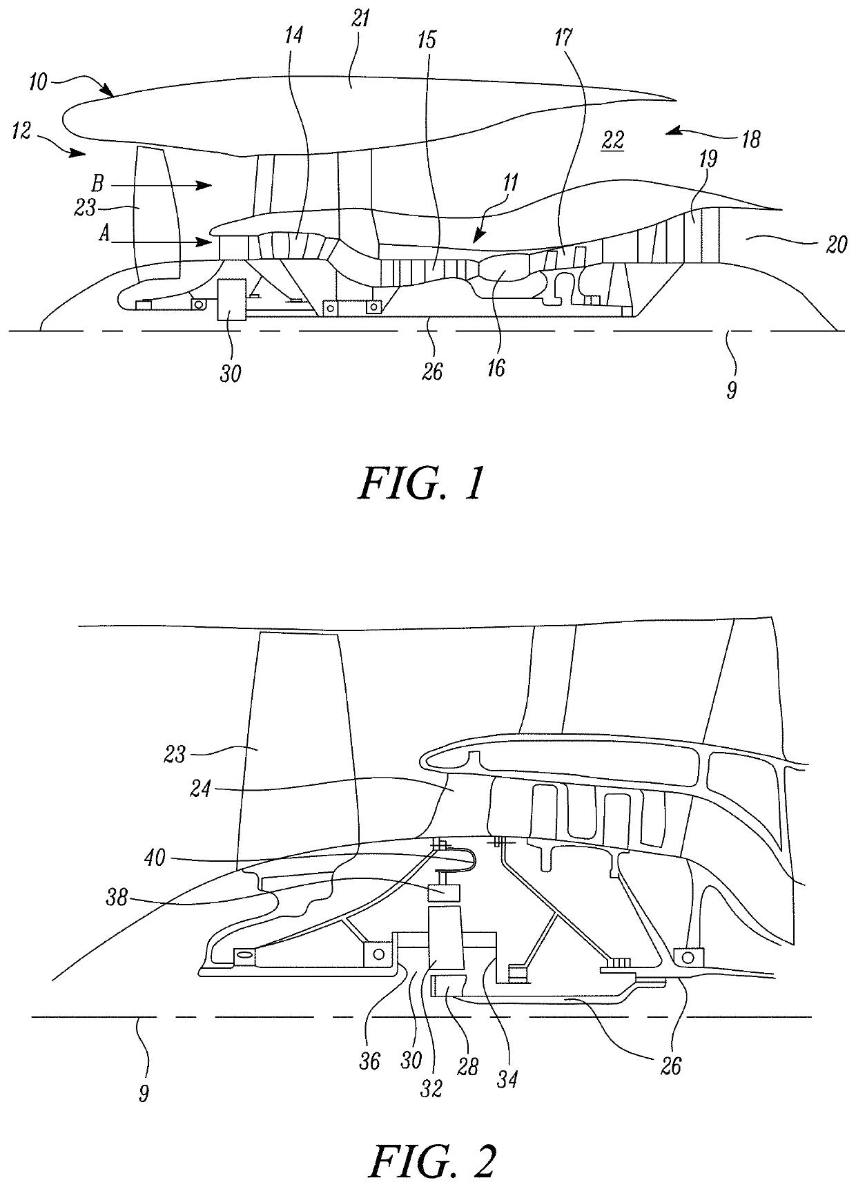
[0091]FIG. 1 illustrates a gas turbine engine 10 having a principal rotational axis 9. The engine 10 comprises an air intake 12 and a propulsive fan 23 that generates two airflows: a core airflow A and a bypass airflow B. The gas turbine engine 10 comprises a core 11 that receives the core airflow A. The engine core 11 comprises, in axial flow series, a low pressure compressor 14, a high-pressure compressor 15, combustion equipment 16, a high-pressure turbine 17, a low pressure turbine 19 and a core exhaust nozzle 20. A nacelle 21 surrounds the gas turbine engine 10 and defines a bypass duct 22 and a bypass exhaust nozzle 18. The bypass airflow B flows through the bypass duct 22. The fan 23 is attached to and driven by the low pressure turbine 19 via a shaft 26 and an epicyclic gearbox 30.

[0092]In use, the core airflow A is accelerated and compressed by the low pressure compressor 14 and directed into the high pressure compressor 15 where further compression takes place. The compres...


PUM


Abstract

A brush seal for sealing a leakage gap in an axial flow path between a relatively higher fluid pressure region and a relatively lower fluid pressure region, that includes an outer housing and an inner housing located at least partially within and configured for radial displacement relative to the outer housing, wherein the upstream facing inner surface of the outer housing is free of any protrusion toward the first downstream facing outer contact surface and second downstream facing outer contact surface.

Description

CROSS-REFERENCE TO RELATED APPLICATIONS[0001]This specification is based upon and claims the benefit of priority from UK Patent Application Number 1814674.6 filed on 10 Sep. 2018, the entire contents of which are incorporated herein by reference.BACKGROUNDField of the Disclosure[0002]The present disclosure concerns a fluid seal. More particularly, the present disclosure concerns a brush seal for sealing a leakage path between relatively movable parts.Description of the Related Art[0003]It is known to use pressure-balanced brush seals and standard plain backing ring brush seals to establish a fluid seal between relatively movable components. Typically, a brush seal comprises a pack of resilient bristles that are fixed to one of the components and are in sliding relationship with the other component. For instance, an annular brush seal positioned in a leakage path between a rotatable shaft and static structure surrounding the shaft. The seal bristles in such an application are normall...

Claims


Application Information

Patent Timeline
Patent Type & Authority Patents(United States)
IPC IPC(8): F16J15/3288F01D11/12F16J15/3276
CPCF16J15/3288F01D11/127F16J15/3276F01D11/001F05D2240/56F05D2260/40311Y02T50/60
Inventor FRANCESCHINI, GERVAS
Owner ROLLS ROYCE PLC
Why Eureka
Try Eureka