Micro turbine for aero-engine

A technology of aero-engines and turbines, which is applied in the direction of engine components, machines/engines, and air transportation, etc. It can solve the problems of easy backward movement of turbine blades and achieve the effects of small vibration stress, high positioning tightness, and long service life

Active Publication Date: 2021-01-08
CHINA HANGFA SOUTH IND CO LTD
View PDF7 Cites 1 Cited by
  • Summary
  • Abstract
  • Description
  • Claims
  • Application Information

AI Technical Summary

Problems solved by technology

[0004] The invention provides a micro-turbine for an aero-engine to solve the technical problem that the turbine blades are easy to move backward when the lock plate is bent and deformed to locate the turbine blades

Method used


Image

  • Micro turbine for aero-engine
  • Micro turbine for aero-engine
  • Micro turbine for aero-engine

Examples


Embodiment Construction

[0027] The embodiments of the present invention will be described in detail below with reference to the accompanying drawings, but the present invention can be implemented in various ways defined and covered below.

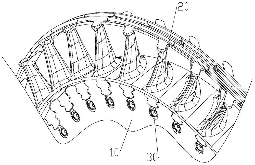
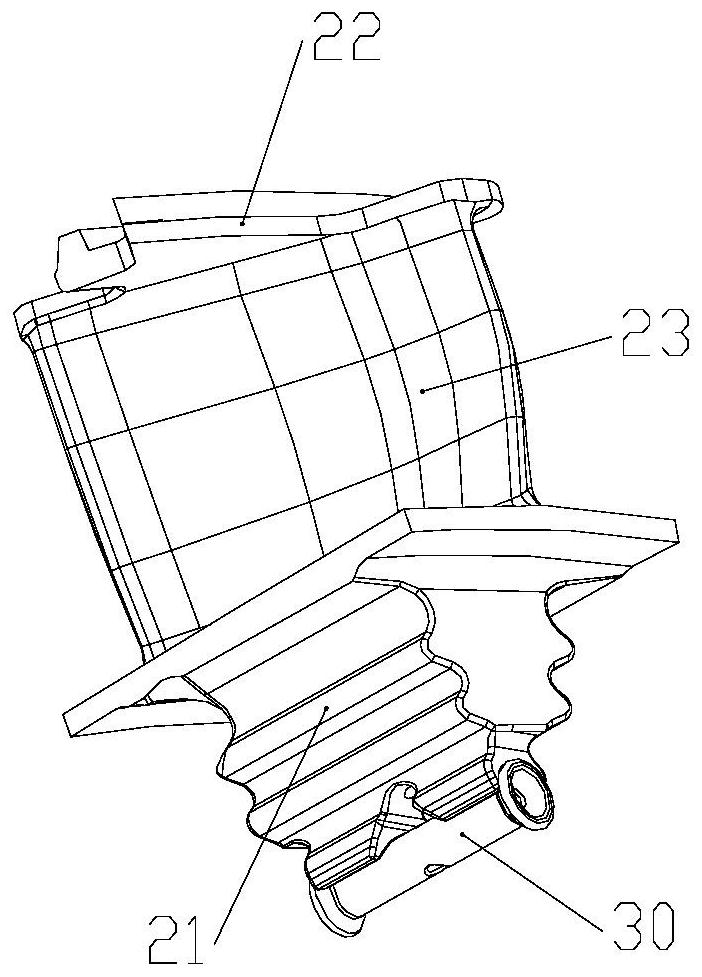
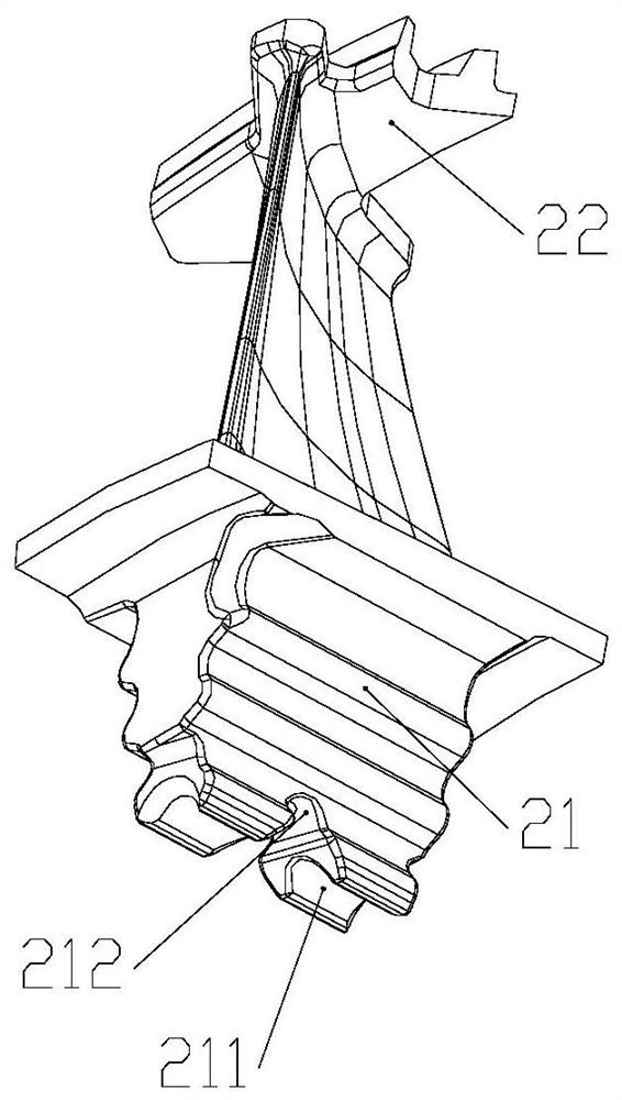
[0028] refer to figure 1 A preferred embodiment of the present invention provides a micro-turbine for an aero-engine, comprising a turbine disk 10 and turbine blades 20 arranged successively on the turbine disk 10 along the circumference of the turbine disk 10, the micro-turbine also includes a The blade 20 is locked to the locking pipe 30 in the corresponding tenon groove 101 on the turbine disk 10. The locking pipe 30 is installed at the connection position between the small end of the tenon 21 of the turbine blade 20 and the tenon groove 101, and the locking pipe 30 It is deformed under the action of external force riveting, so as to be squeezed into the tenon 21 and the tenon groove 101 at the same time to lock the turbine blade 20, thereby preventing the turb...


PUM

PropertyMeasurementUnit
Diameteraaaaaaaaaa

Abstract

The invention discloses a micro turbine for an aero-engine. The micro turbine comprises a turbine disc, and turbine blades sequentially distributed on the turbine disc along the circumferential direction of the turbine disc, wherein the turbine disc further comprises locking pipes used for locking the turbine blades in corresponding mortises on the turbine disc; the locking pipe is arranged at theconnecting position of the small end of a tenon and the mortise of the turbine blade; and the locking pipe deforms under the action of external force punching and riveting so as to be squeezed in thetenon and the mortise at the same time to lock the turbine blade, and then the turbine blade is prevented from moving backwards towards the exhaust end of the turbine. According to the micro turbinefor the aero-engine, due to the fact that deformation of the locking pipes under the action of punching and riveting force is spatial multi-dimensional deformation, the positioning locking tightness of the locking pipes to the turbine blades is larger than the locking tightness of locking pieces, and therefore the turbine blade can be effectively prevented from moving backwards towards the exhaustend of the turbine, and then the breaking fault of the turbine blade occurring after the turbine blade scrapes a rear stator is reduced; and the turbine blades are high in positioning tightness, so that the fretting wear of the tenon contact surface is small, and the vibration stress of the tenon contact surface is small.

Description

technical field [0001] The invention relates to the field of aero-engines, in particular to a micro-turbine for aero-engines. Background technique [0002] The turbine blades of aero turbine engines are key life-defining parts, and their working environment is extremely harsh. The turbine blades must withstand high temperature and high speed gas corrosion, and bear huge centrifugal force and aerodynamic force, as well as vibration and thermal stress. Turbine blade failure is catastrophic to the engine and seriously endangers flight safety. Therefore, turbine blades that exceed the number of service hours or cycles must be scrapped. The structure, material, surface treatment, cooling scheme, design technology, manufacturing process, testing technology and other aspects of turbine blades are protected by numerous intellectual property rights. Long-life, high-efficiency aero-engine turbines basically adopt a blisk-disk combination structure, that is, the turbine blades are ins...

Claims


Application Information

Patent Timeline
IPC IPC(8): F01D5/18F01D5/14F01D5/26F01D5/32
CPCF01D5/141F01D5/147F01D5/32F01D5/186F01D5/26Y02T50/60
Inventor 刘飞亭彭煜徐皓珉雷霄玉
Owner CHINA HANGFA SOUTH IND CO LTD
Why Eureka
Try Eureka