
Fixing device

A fixing device and screw fixing technology, which is applied in threaded fasteners, thin plate connections, connecting components, etc., can solve problems such as deformation of the inner hook A2, difficulty in assembly, cracking and bending of the inner hook A2 or flange B1, and achieve accurate Reliable snap-fit ​​assembly, high positioning tightness, and easy assembly

Inactive Publication Date: 2011-04-20
TECHMECH TECH CORP
View PDF0 Cites 0 Cited by
  • Summary
  • Abstract
  • Description
  • Claims
  • Application Information

AI Technical Summary

Problems solved by technology

[0005] Although the manufacturing process of the above-mentioned fastening screws can achieve the effect of locking and fixing the positioning plate body D and the fixing plate body D1, there are still the following imperfections. The cap A and the fixing seat B are both made of metal steel body, and the outer diameter of the nut A11 at the top of the screw A1 and the flange B1 of the fixing seat B is larger than the inner diameter of the inner hook A2 of the cap A. When the screw A1 and the fixing seat B are to be assembled into the cap A, they must Apply strong pressure to fix the nut A11 and the flange B1 in the inner hook A2 of the metal sleeve cap A for positioning, which makes assembly difficult, and this way of pressurized assembly is easy to fix The flange B1 of the seat B or the inner hook A2 of the cap A is deformed, which makes the inner hook A2 or the flange B1 cracked and bent, which affects the overall assembly relationship and the joint effect is not reliable.

Method used


Image

  • Fixing device
  • Fixing device
  • Fixing device

Examples


Embodiment Construction

[0061] The detailed description is as follows in conjunction with the embodiments and accompanying drawings.

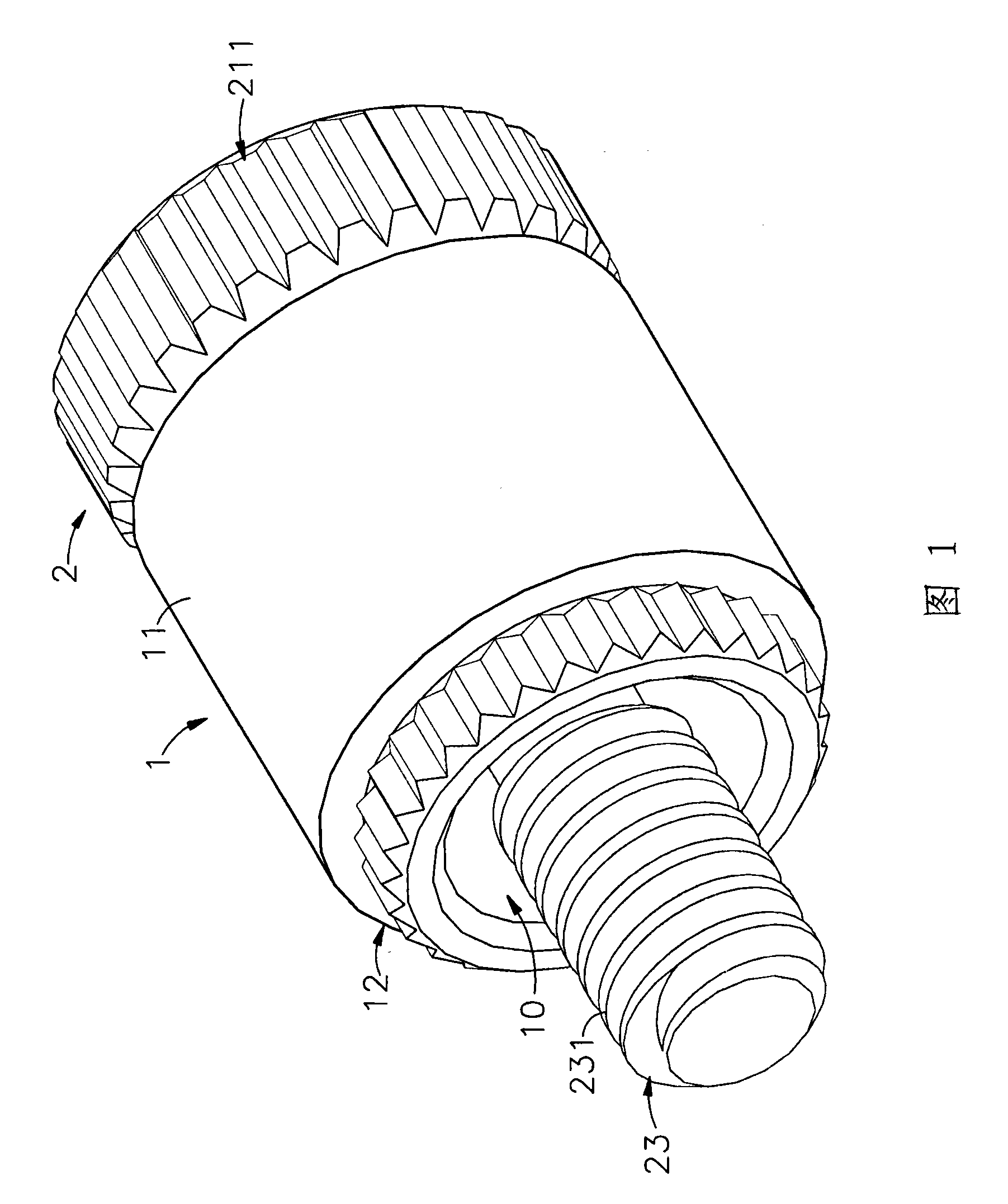
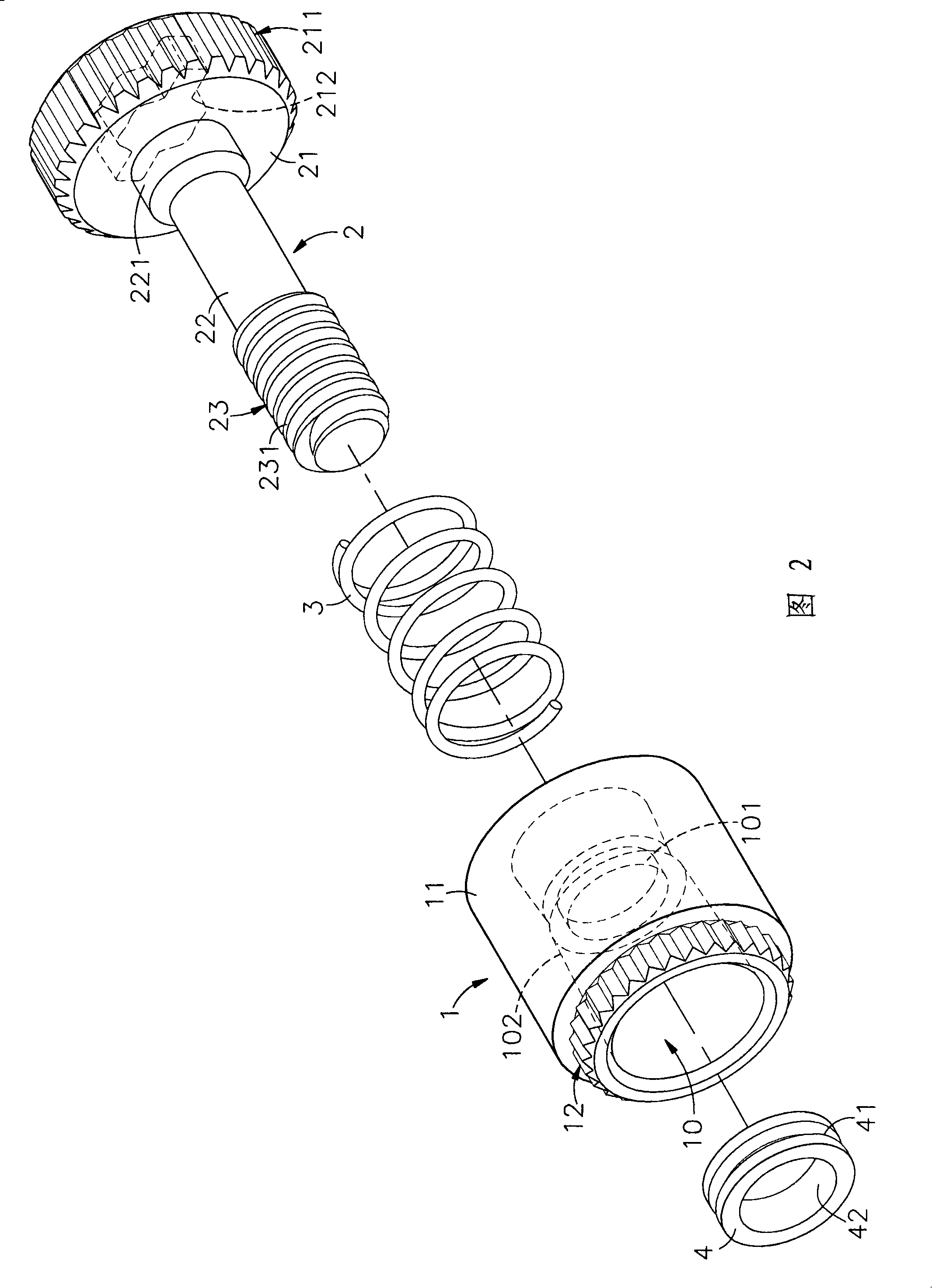
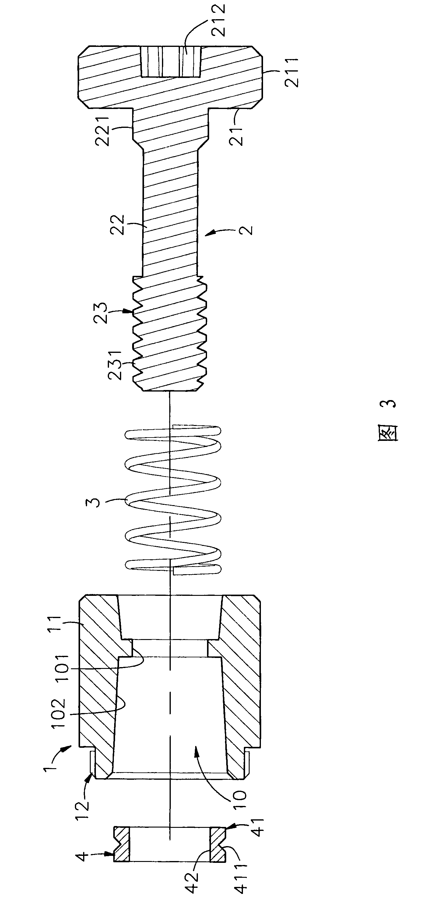
[0062] Please refer to Fig. 1, Fig. 2 and Fig. 3, which are the three-dimensional appearance diagram, the three-dimensional exploded view and the side view sectional view before assembly of the present invention. It can be clearly seen from the figure that the fixing device of the present invention has The receiving pipe body 1, the screw assembly 2, the spring 3 and the stop collar 4 are composed, and the structure of the present invention is described in detail below; wherein:

[0063] The receiving pipe body 1 is formed with a perforation 10 in the hollow pipe body 11, and the inner wall surface of the perforation 10 is protruded with a ring convex part 101 and an inwardly tapered slope 102, and another side of the receiving pipe body 1 is provided with a Engagement part 12.

[0064] The screw fixing component 2 is formed with an engaging portion 211 on the outer ...


PUM


Abstract

The invention discloses a fixing device, which comprises a socket pipe body, a screw fixing component, a spring and a backstop lantern ring. The inner wall surface of a perforation of the socket pipe body is convexly provided with a ring convex part; the screw fixing component is provided with a gyration head end which can be propped against the upper surface of the socket pipe body; and the bottom surface of the gyration head end is downwards extended with a sleeve joint spring and the sleeve joint spring is inserted into a rod body positioned in the perforation, two sides of the spring are butted to the bottom surface of the gyration head end and the ring convex part respectively, and the tail end of the rod body is provided with a screw connection part which is protruded out of the perforation and sleeved into the backstop lantern ring. When the backstop lantern ring is packed in the perforation of the socket pipe body by an extrusion acting force, the backstop lantern ring self isreduced and deformed in the perforation of the socket pipe body so that the diameter of an internal circle of the backstop lantern ring is smaller than that of an external circle of the screw connection part, and then the backstop lantern ring has the effect of blocking the screw connection part from being separated from the outside of the perforation of the socket pipe body. The fixing device has the effects of simple, easy, quick and convenient assembly; and meanwhile, the backstop lantern ring can achieve the effects of firm combination, high positioning compactness, difficult dropping andfirm accurate buckling by using the properties of a metal material for the backstop lantern ring.

Description

technical field [0001] The invention relates to a fixing device, which belongs to the technical field of mechanical fixing in daily life, industrial products and electronic products, specifically belongs to the technical field of plate-to-board mechanical fixing in daily life, industrial products and electronic products. Background technique [0002] The general panel (board-to-board) locking is locked by screws with knobs, collars and screws. It is to fix the screws and collars on the first panel first, and turn the knob to lock the screws into the second panel. In the panel, finally tighten the screws with a tool, so that the first panel and the second panel can be locked together, which can be used on a working machine or other board-to-board connections. [0003] However, as far as the power device or speed adjustment device of the above-mentioned working machine is concerned, it is all located in the housing, so in order to allow the user to facilitate maintenance when ...

Claims


Application Information

Patent Timeline
Patent Type & Authority Patents(China)
IPC IPC(8): F16B5/02F16B23/00
Inventor 邱明忠
Owner TECHMECH TECH CORP
Learn More