Direct memory access system and method

a direct memory and access system technology, applied in the field of direct memory access system and method, can solve the problems of low re-utilization of circuits to increase the number of buses, save a lot of time for a processor to execute programs, and reduce the number of buses. , the effect of increasing the bandwidth and improving the transmission efficiency

Inactive Publication Date: 2010-11-16
SONIX TECH
View PDF6 Cites 1 Cited by
  • Summary
  • Abstract
  • Description
  • Claims
  • Application Information

AI Technical Summary

Benefits of technology

[0008]In light of the above-mentioned problem, one object of the invention is to provide a direct memory access (DMA) system and a DMA method that can improve the transmission efficiency and maintain high expandability for the buses and channels of the DMA system.
[0011]According to the DMA system and the DMA method described in the embodiments of the invention, since the read bus, the write bus, and the buffer memory bus are shared by a plurality of peripheral devices, the transmission efficiency is improved and the number of buses can be reduced. Besides, when the bandwidth is required to be increased, the DMA architecture of the invention makes it easy to add more buses thereto and simplifies the connection between peripheral devices and buses. Moreover, the design of transmitting channels is more flexible and has high expandability. Further, under the DMA configuration according to the invention, the buffer memory can be shared by different peripheral devices for temporary storage to thus save memory space and chip areas as a result. Therefore, the allocation of memory space can be centralized to promote the utilization of memories.

Problems solved by technology

Therefore, it would save much time for a processor to execute programs.
However, according to the DMA configuration shown in FIG. 2, during data transmission, it is difficult for the peripheral devices 21, 22, 23, and 24 to share the same buffer memory for temporary storage.
In addition, such DMA configuration may result in low re-utilization of circuits to increase the number of buses as long as the space of buffer memories when more peripheral devices are incorporated therein.
Under the circumstance, it becomes even more difficult to modify the hardware design.

Method used


Image

  • Direct memory access system and method
  • Direct memory access system and method
  • Direct memory access system and method

Examples


Embodiment Construction

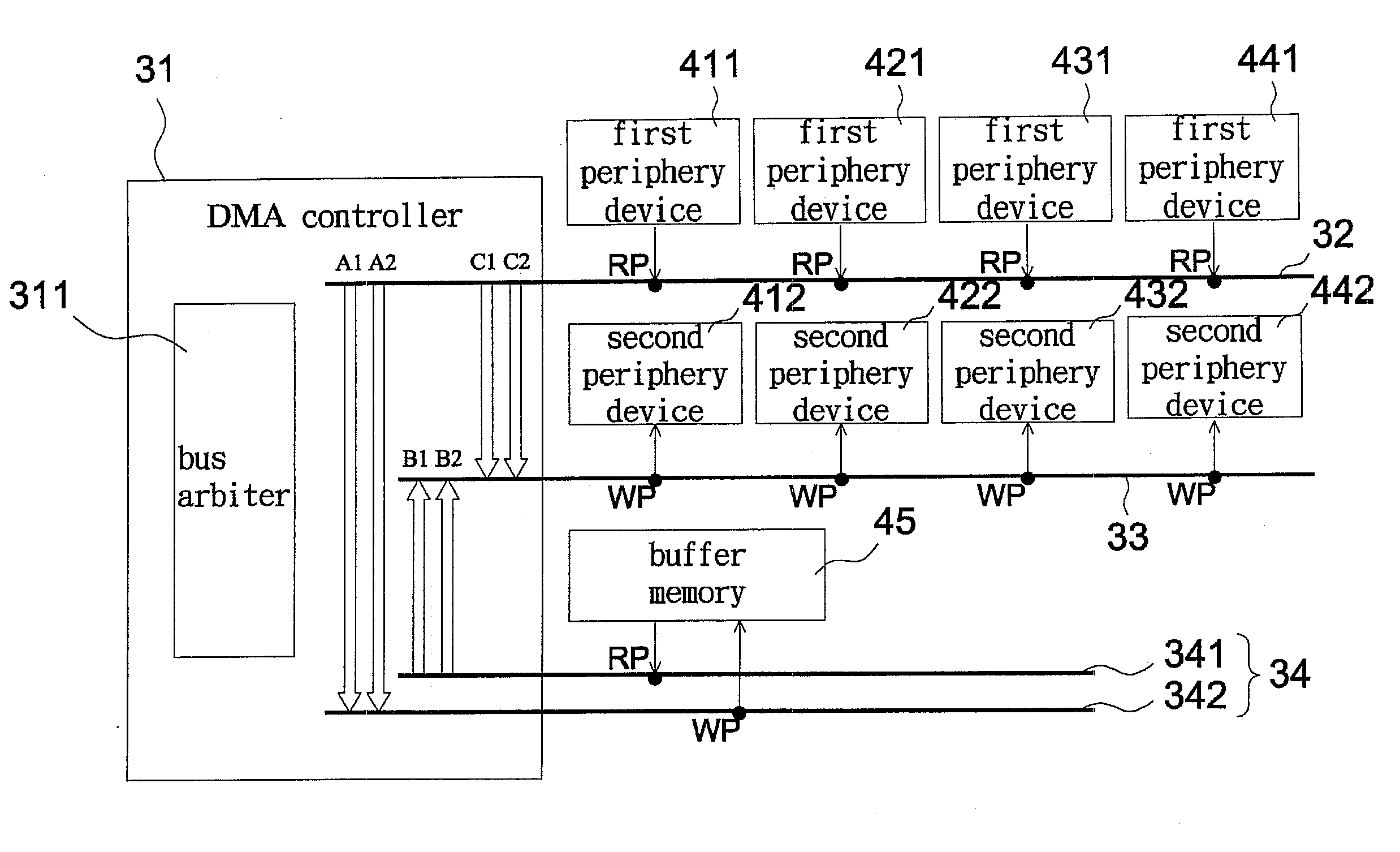
[0017]Referring to FIG. 3, one direct memory access system, according to an embodiment of the invention, includes at lease one read bus 32, at least one write bus 33, at least one buffer memory bus 34, and a direct memory access (DMA) controller 31. As shown in FIG. 3, the read bus 32 is electrically connected to first peripheral devices 411, 421, 431, and 441 for reading data from the first peripheral devices 411, 421, 431, and 441. The read bus 32 has at least one read port RP, preferably a plurality of read ports RP. The write bus 33 is electrically connected to the second peripheral devices 412, 422, 432, and 442 for writing data to the second peripheral devices 412, 422, 432, and 442. The write bus 33 has at least one write port WP, preferably a plurality of write ports WP.

[0018]It should be noted that the first peripheral device and the second peripheral device can be the same. For example, the first peripheral device 411 and the second peripheral device 412 are the same perip...


PUM


Abstract

A DMA system includes at lease one read bus, at least one write bus, at least one buffer memory bus, and a DMA controller. The DMA controller comprises a plurality of channels and a bus arbiter. The channels are electrically connected to the read bus, the write bus, and the buffer memory bus. A source address and a destination address of data for each channel are assigned by a control table. The bus arbiter performs bus arbitration and prioritizes data access among the read bus, the write bus, and the buffer memory bus.

Description

CROSS REFERENCE TO RELATED APPLICATION[0001]This application claims priority of application No. 096142946 filed in Taiwan R.O.C on Nov. 14, 2007 under 35 U.S.C. §119; the entire contents of which are hereby incorporated by reference.BACKGROUND OF THE INVENTION[0002]1. Field of the Invention[0003]The invention relates to a direct memory access (DMA) system and method, particularly to a DMA system and a DMA method having improved transmission efficiency and high expandability.[0004]2. Description of the Related Art[0005]Direct memory access (DMA) allows direct data transfer between a peripheral device and a memory without the participation of a processor like CPU. The large amount of data transfer between the peripheral device and the memory by way of direct memory access (DMA) does not need any interrupt service from an interrupt service routine and is completed via hardware. Therefore, it would save much time for a processor to execute programs.[0006]As shown in FIG. 1, a DMA contro...

Claims


Application Information

Patent Timeline
Patent Type & Authority Patents(United States)
IPC IPC(8): G06F13/28
CPCG06F13/28G06F13/362
Inventor HUANG, YIN-HSIHUANG, CHUN-JIEH
Owner SONIX TECH
Why Eureka
Try Eureka