Vacuum cleaner with hand grip and adapter

a technology of adapter and vacuum cleaner, which is applied in the direction of application, household cleaner, vehicle maintenance, etc., to achieve the effect of favorable elastic adaptation and high stiffness and impact strength

Inactive Publication Date: 2010-11-23
FISCHER ROHRTECHN
View PDF12 Cites 2 Cited by
  • Summary
  • Abstract
  • Description
  • Claims
  • Application Information

AI Technical Summary

Benefits of technology

[0008]Moreover, with its one end it completely surrounds the region of the vacuum cleaner suction pipe facing it, and not as in the prior art, only on a small peripheral region, and is braced in final mounting without wobbling relative to this end region of the vacuum cleaner suction pipe via a screw connection, and thus, is connected positively and nonpositively to the vacuum cleaner suction pipe. By its complete and thus protective twisting of the end region of the vacuum cleaner suction pipe, the entire vacuum cleaner acquires not only a durable, but also an optically pleasing shape.
[0011]According to one especially advantageous development of the invention, the adapter is formed altogether of three shells which are connected to one another via two film hinges which run parallel to the lengthwise axis of the vacuum cleaner suction pipe. Of them, the two outer shells are roughly the same and the middle shell is made in the form of a strip. The inner side of all of the shells has the shape of pitch circle segments which in their end mounting position circularly surround the end region of the vacuum cleaner suction pipe held by them and the pipe socket of the handle. In this way, this end region of the vacuum cleaner suction pipe is also protected by the adapter against deformation.
[0012]Furthermore, the adapter, by circularly surrounding the end region, adapts both to the shape of the vacuum cleaner suction pipe and also that of the handle with the result that not only a durable, detachable coupling, but also an optically pleasing connection between the handle and the vacuum cleaner suction pipe are formed.
[0014]The middle part of the shell is advantageously provided in its middle region with a button molded in the shape of a leaf spring for pressing down the locking means on the pipe socket. In the prior art, this button has been located opposite the adapter on the outer periphery of the vacuum cleaner suction pipe, and thus, it required additional attachment. In this way, the vacuum cleaner suction pipe remains smooth without a rivet connection and matches the overall impression in terms of streamlining and in an optically favorable manner.
[0015]To achieve high stiffness and impact strength, in spite of saving material in the configuration of the wall thicknesses, the shells are provided with stiffening ribs on their insides. These stiffening ribs are made in the shape of a pitch circle on their free ends in order to be able, accordingly, to favorably adapt elastically to the outside diameter of the end region of the vacuum cleaner suction pipe by bracing.
[0018]For simple and economical production, shells are produced from plastic, especially from polyamide (PA) or polypropylene (PP). The vacuum cleaner suction pipe can be made in the conventional manner as a telescoping pipe.

Problems solved by technology

If this adapter is exposed to bending or impact forces, for example, when placed abruptly on the floor or when the vacuum cleaner suction pipe is improperly coupled or supported, the adapter can break off, with the result that, then, not only the adapter, but the complete vacuum cleaner suction pipe must be replaced by a new one.

Method used


Image

  • Vacuum cleaner with hand grip and adapter
  • Vacuum cleaner with hand grip and adapter
  • Vacuum cleaner with hand grip and adapter

Examples


Embodiment Construction

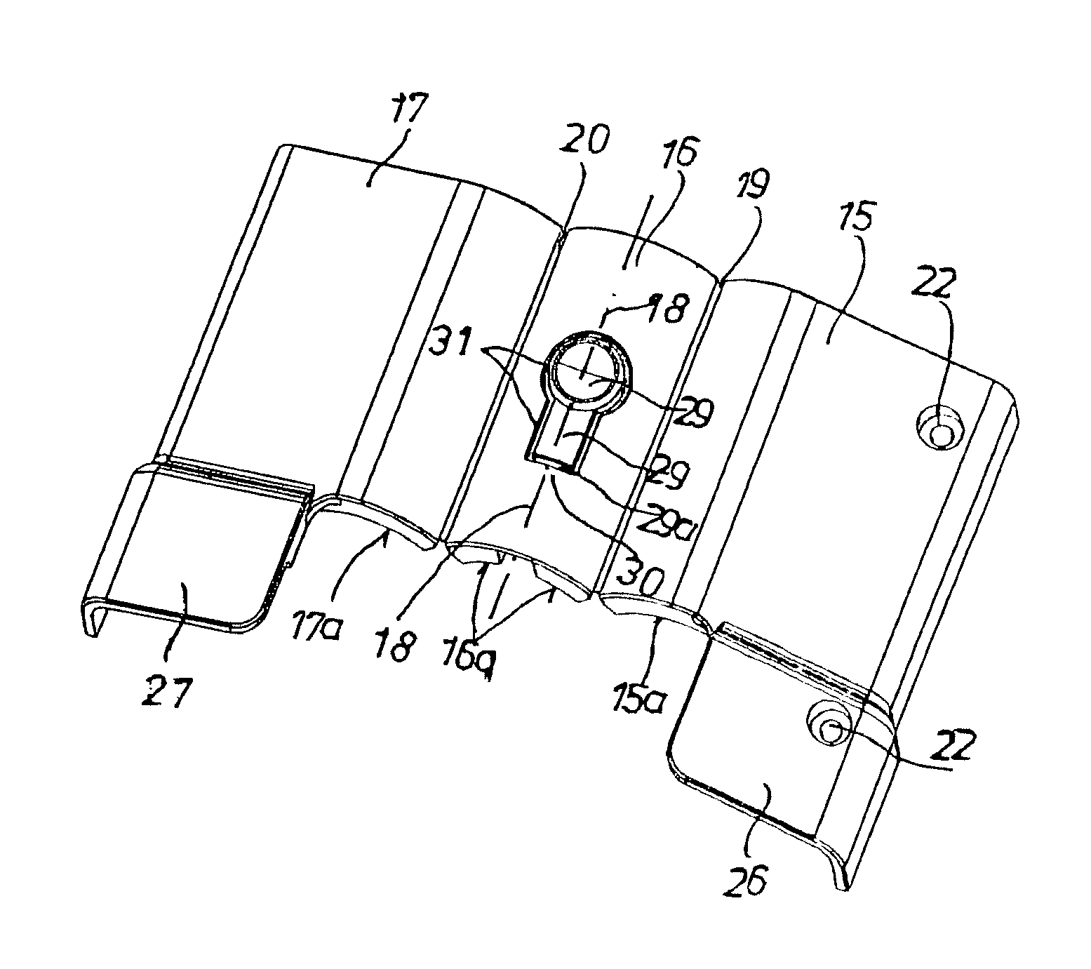
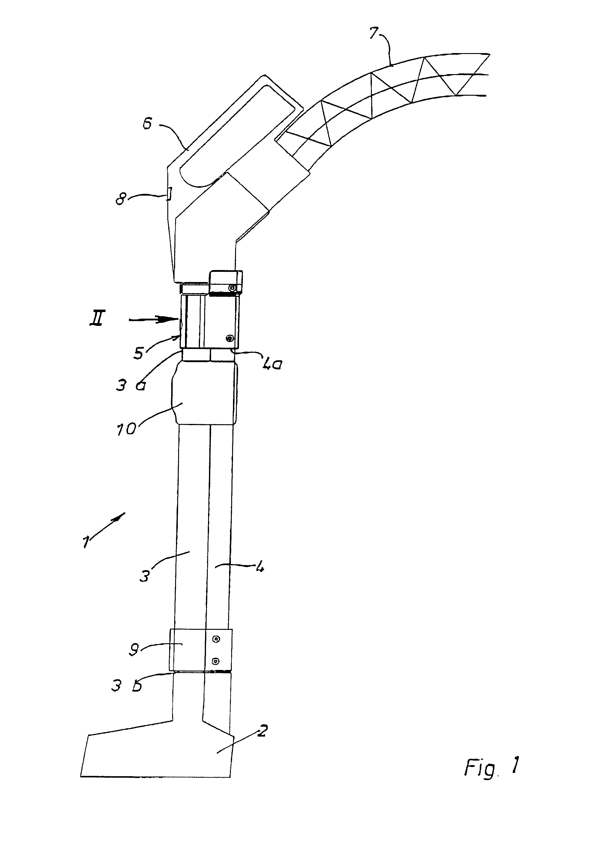
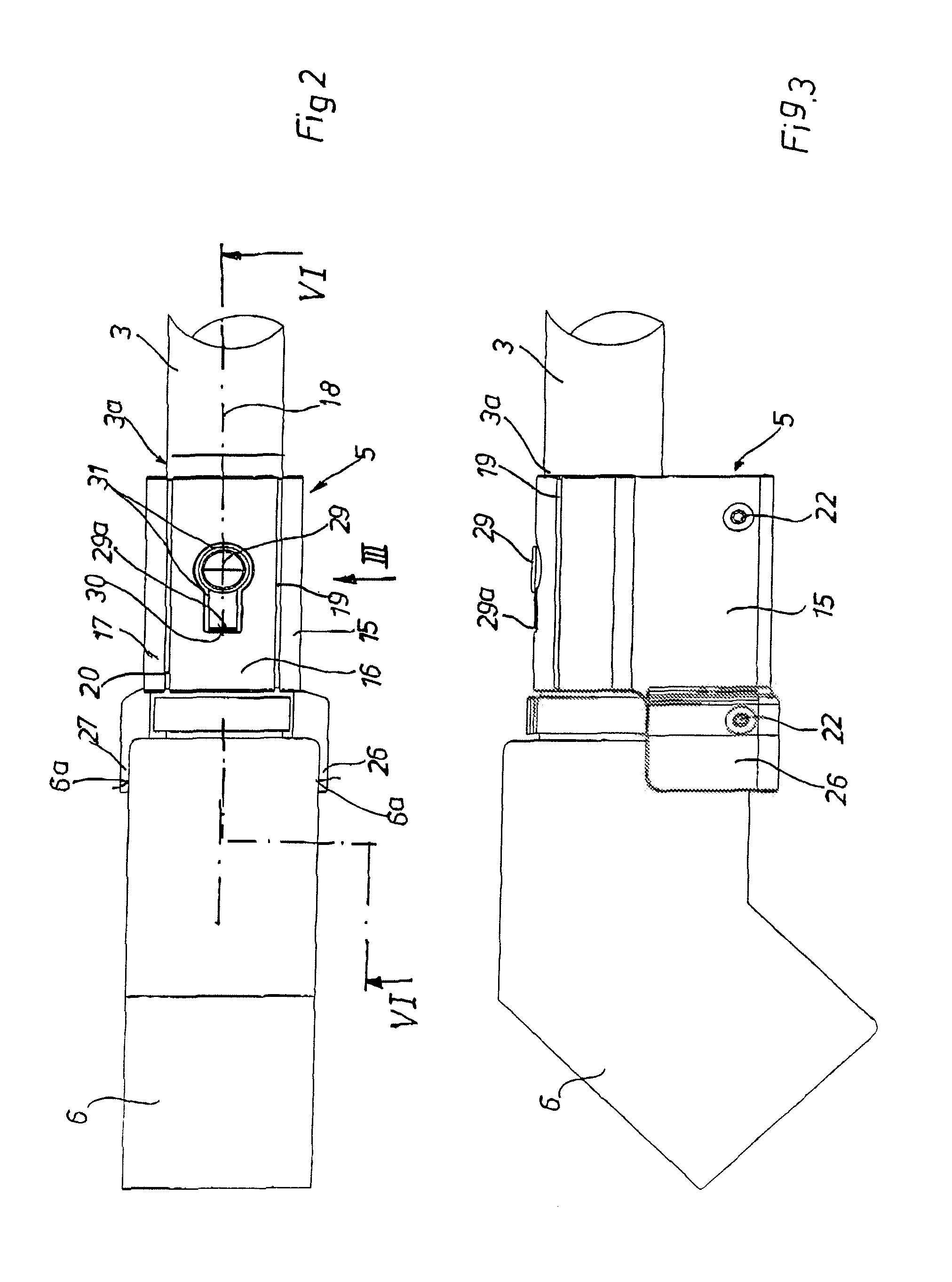
[0039]As shown in FIG. 1, the vacuum cleaner 1 comprises a nozzle 2, a vacuum cleaner suction pipe 3, a cable channel 4, an adapter 5, a handle 6 and a flexible hose 7. For example, in order to be able to actuate a brush which is present on the nozzle 2 and which is driven by an electric motor, an electrically conductive connection from the nozzle 2 via the cable channel 4 of the vacuum cleaner suction pipe 3, the adapter 5, the handle 6 and via a flexible hose 7 to the power supply of an intake radial fan (not shown) must be ensured. This electrically conductive connection can be turned on and off via a switch 8 which is attached to the handle 6. The cable channel 4 is held on the vacuum cleaner suction pipe 3 by a clamp 9 and a slider 10 and by one end of the adapter 5.

[0040]In order to be able to detach the vacuum cleaner suction pipe 3 with its adapter 5 from the handle 6 after use, in the prior art, the locking pin 13 (FIGS. 4, 5, &5a) had to be pushed down for unlocking by a b...


PUM


Abstract

A vacuum cleaner with a handle and an adapter accommodates the end region of the vacuum cleaner suction pipe at one end and the pipe socket of the handle at the other end is improved by the adapter being of a durable construction that does not require a new vacuum cleaner suction pipe when the adapter is broken is achieved by the adapter being formed of at least two shells which are pivotably connected together via a film hinge which runs parallel to the lengthwise axis of the vacuum cleaner suction pipe and by their free end regions having a screw connection by which the adapter is detachably braced against the facing end region of the vacuum cleaner suction pipe in the mounted position of the adapter.

Description

BACKGROUND OF THE INVENTION[0001]1. Field of the Invention[0002]The invention relates to a vacuum cleaner with a handle and adapter which accommodates the end region of the vacuum cleaner suction pipe on one end and the pipe socket of the handle on its other end, and is coupled to the pipe via a detachable locking means, via electrical couplings there being an electrically conductive connection from the nozzle on the free end of the vacuum cleaner suction pipe, via the vacuum cleaner suction pipe, the adapter, the handle, and the flexible vacuum hose to the power supply of the vacuum cleaner.[0003]2. Description of Related Art[0004]This type of vacuum cleaner has been used in the United States for a long time and is in use. In the vacuum cleaner according to the prior art, the adapter is formed of a plastic strip which extends positively under the lower part of the end region of the vacuum cleaner suction pipe and which projects with an extension which is U-shaped in cross section o...

Claims


Application Information

Patent Timeline
Patent Type & Authority Patents(United States)
IPC IPC(8): A47L9/24
CPCA47L9/246A47L9/327
Inventor CORDES, MARTINCORDES, STEPHAN
Owner FISCHER ROHRTECHN
Why Eureka
Try Eureka