Rotary expansion

a technology of expansion tool and rotary expansion plate, which is applied in the direction of shaping tools, wellbore/well accessories, lighting and heating apparatus, etc., can solve the problems of restricting the combination of bearing pressure and velocity, and achieves the effects of large bearing area, large area, and large bearing area

Active Publication Date: 2010-11-23
WEATHERFORD TECH HLDG LLC
View PDF15 Cites 6 Cited by
  • Summary
  • Abstract
  • Description
  • Claims
  • Application Information

AI Technical Summary

Benefits of technology

[0013]Providing a self-contained sealed lubrication system within the spindle facilitates provision of a compact expansion member which has its primary bearing surface lubricated and isolated from well materials. This has the effect of reducing failure and extending the life cycle of the expansion member.
[0016]Preferably, faces of the spindle or roller define a bearing contact area of substantially the same extent as, or greater area than, the axial faces of the bearing. This arrangement thus serves to minimise or prevent axial extrusion of the bearing.
[0018]The sealed lubrication system may comprise a lubricant reservoir in fluid communication with the at least one bearing, which lubricant reservoir may be defined by the spindle. The lubrication system may be arranged to urge lubricant from the reservoir towards said bearing or bearing surface. This arrangement facilitates continued lubrication of the tool in the event of loss or leakage of lubricant. This may be achieved by providing a variable volume reservoir with a wall or walls of the reservoir adapted to be urged to reduce the volume of the reservoir, for example a wall of the reservoir may be spring-biased to urge lubricant from the reservoir. The reservoir may comprise a cylindrical volume within the spindle. One end of the volume may comprise a piston member adapted to move along the axis of the volume. In one embodiment the axes of the volume and the cylinder are parallel, and may be coaxial, while in another embodiment the axes are mutually perpendicular or inclined.
[0022]Pressure balance or equalisation may be maintained between the bearing lubrication system and external or ambient pressure by a valve which permits communication of external pressure, for example annulus or bore pressure, to the lubricant. The valve may be a poppet valve. Alternatively, pressure is communicated to the system by means of a diaphragm or floating piston. Accordingly, there is little or no pressure differential across the lubricant-retaining seals. In other embodiments it may be preferred to maintain the lubricant at a positive pressure, higher than external pressure, to minimise ingress of external material.
[0037]An outer or proximal portion of the spindle and the carrier may define corresponding profiles, for example dovetail profiles, to provide for radial restraint of the spindle relative to the carrier. This contrasts with arrangements in which both ends of the spindle are received in bores in the carrier. Particularly when inclined axis rollers are utilised, the necessity to provide a bore to receive the radially outermost end of the spindle, and through which the rest of the spindle must pass, places restrictions on the spindle, carrier and roller form. Where the outer end of the spindle is fixed to the carrier by other means, preferably by providing a spindle with an outer integral profiled portion which cooperates with a corresponding profile on the carrier, the portion of the spindle within the roller may include relatively large diameter bearing portions. This offers numerous advantages, including a spindle of greater strength and rigidity, provision of a larger bearing area, and provision of relatively large area thrust bearings between spindle portions of different diameter, which thrust bearings may be provided within the roller, spaced from the ends of the spindle. Where the expansion member incorporates a sealed lubrication system, such as described above with reference to the first aspect of the invention, the thrust bearings may thus be located within the lubricated portion of the roller. In such embodiments, the provision of a larger diameter spindle allows for a larger volume of lubricant to be provided within the spindle, and with little or no adverse effect on spindle rigidity and robustness.
[0042]Assembly of such an expansion member is likely to be easier than if it was necessary to locate the roller on the carrier before locating the spindle in the roller. Furthermore, when the member incorporates a sealed lubrication system, or indeed any bearing arrangement, the ability to assemble the spindle and roller before the roller is mounted on the carrier offers a number of advantages. For example, if an operator wishes to replace a roller or spindle in the field, a pre-assembled spindle / roller unit may be utilised. This unit may have been assembled in a clean, controlled environment, thus avoiding or minimising the risk of contamination or damage, which is far more likely to occur if the roller and spindle must be assembled on a carrier in the field.

Problems solved by technology

Furthermore, the use of an unlubricated bearing system restricts the combination of bearing pressure and velocity which can be withstood without degradation and thermal damage.

Method used


Image

  • Rotary expansion
  • Rotary expansion
  • Rotary expansion

Examples


first embodiment

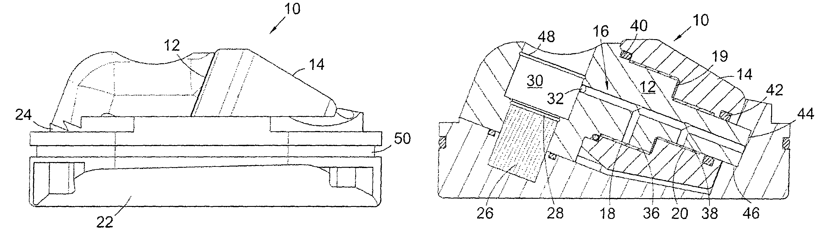
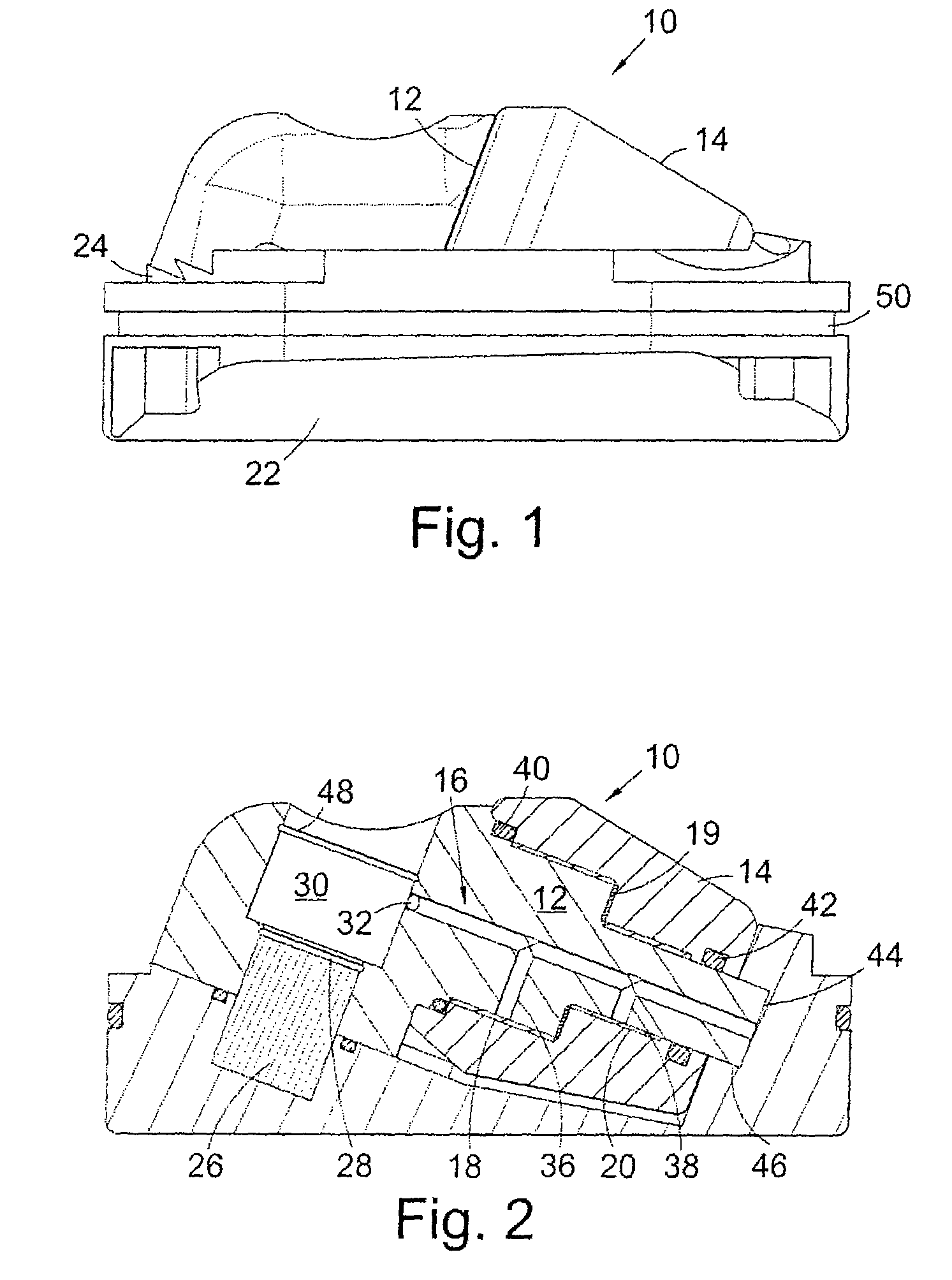
[0059]Referring firstly to FIGS. 1 and 2, a side view and a cross-sectional side view of an expansion member, generally indicated by reference numeral 10, according to the present invention.

[0060]The expansion member 10 is adapted to be fitted to a downhole expansion tool (not shown), generally as one of a set of three expansion members 10 spaced at 120° intervals around the circumference of the tool.

[0061]The expansion member 10 includes a spindle 12 and a roller 14 mounted concentrically on the spindle 12. The spindle 12 is coupled to an expansion member carrier 22 by a dovetail groove connection 24 aligned with the spindle axis. To assemble expansion member 10, the spindle 12 is slid along the dovetail groove 24 into the roller 14 until the spindle end 44 engages a carrier recess 46, or more preferably the spindle 12 and roller 14 are assembled before the spindle 12 is made up to the carrier 22. The spindle 12 is then pinned in position using a stop pin 26 and a circlip 28 (FIG. ...

second embodiment

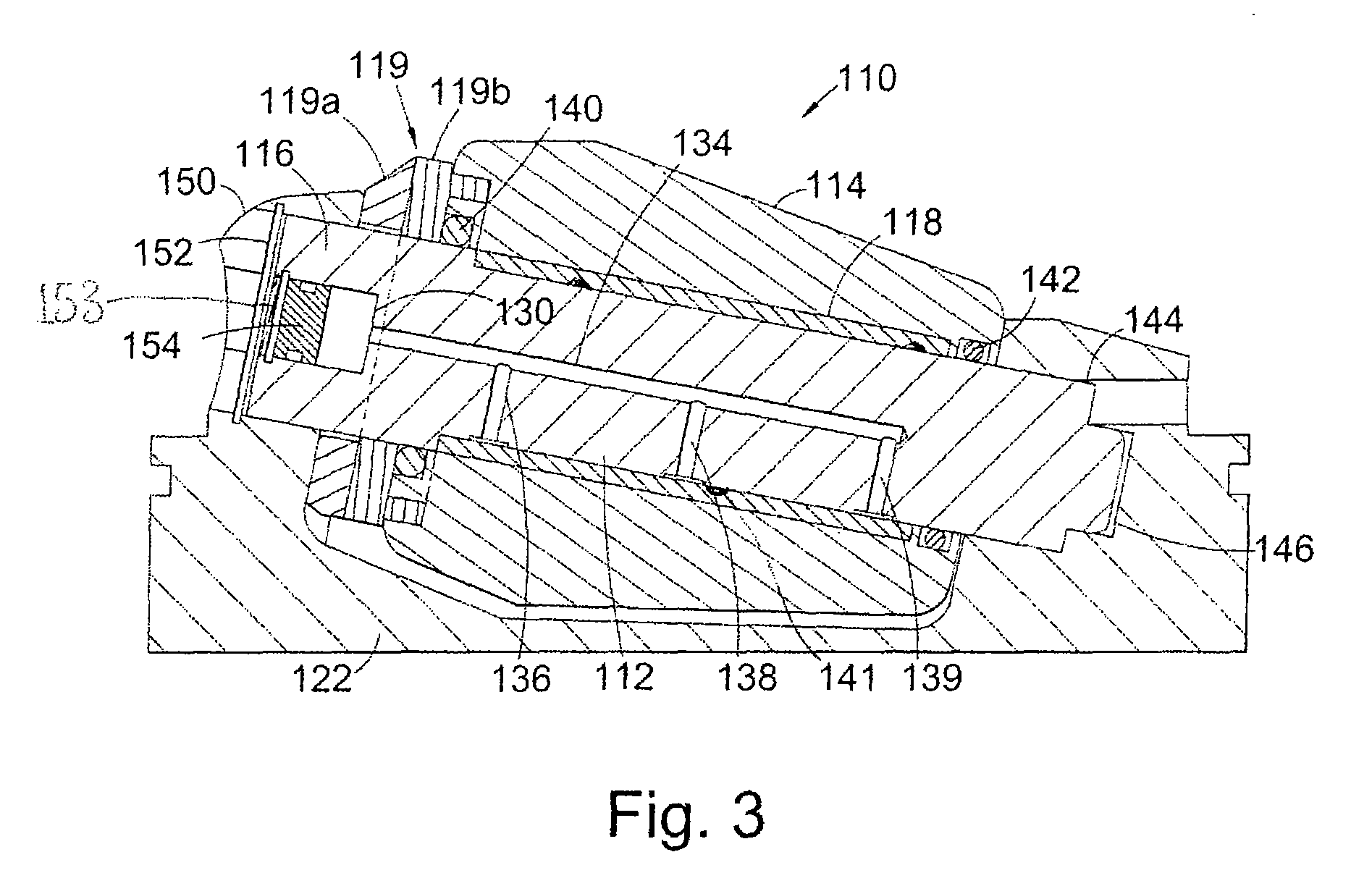
[0068]Referring now to FIG. 3, there is shown a cross-sectional side view of an alternative expansion member 110 according to the present invention, FIGS. 4, 5 and 6 showing the member 110 mounted in an expansion tool.

[0069]The expansion member and tool share many features with the tools described in applicant's US Patent Application Publication No. US 2005 / 0072569, which is herein incorporated by reference in its entirety.

[0070]The expansion member 110 comprises a spindle 112 and a roller 114 mounted concentrically on the spindle 112. The spindle 112 is supported at both ends and the roller is mounted between the supported ends. The expansion member 110 is assembled by passing the spindle 112 through a throughbore 150 defined by a carrier 122, and through the roller 114. The spindle end 144 engages a housing recess 146 defined by the carrier 122 and is secured in position by, for example, a circlip 152.

[0071]The expansion member 110 also includes a sealed lubrication system 116 con...


PUM

PropertyMeasurementUnit
areaaaaaaaaaaa
cylindrical volumeaaaaaaaaaa
volumeaaaaaaaaaa

Abstract

An expansion member for a rotary expansion tool comprises a spindle adapted to be supported at both ends, and a roller mounted concentrically on the spindle. A sealed lubrication system is contained within the spindle for supplying lubricant to a bearing or bearing surface at an interface between the spindle and the roller.

Description

CROSS-REFERENCE TO RELATED APPLICATIONS[0001]This application claims benefit of Great Britain patent application serial number 0520859.0, filed Oct. 14, 2005, which is herein incorporated by reference.BACKGROUND OF THE INVENTION[0002]1. Field of the Invention[0003]The present invention relates to rotary expansion tools for expanding tubing. In particular, but not exclusively, the present invention relates to an improved expansion member for a rotary expansion tool.[0004]2. Description of the Related Art[0005]A number of different tools have been proposed for carrying out expansion of downhole tubing such as expandable bore-lining tubing and expandable sand screens. Applicant's International Patent Application Publication No WO 2000 / 37766, the disclosure of which is incorporated herein by reference in its entirety, discloses a rotary expansion tool including a number of expansion members in the form of rollers mounted on radially moveable pistons. Fluid pressure urges the pistons rad...

Claims


Application Information

Patent Timeline
Patent Type & Authority Patents(United States)
IPC IPC(8): B21D3/02B21D37/00B21B45/02B21D41/02E21B43/10
CPCB21D41/023E21B43/105B21D39/10E21B29/10
Inventor JOHNSTON, GARY
Owner WEATHERFORD TECH HLDG LLC
Why Eureka
Try Eureka