
Fluid loss concentrate for hydraulic cement

a technology of hydraulic cement and fluid loss concentrate, which is applied in the direction of colloidal chemistry, transportation and packaging, mixing, etc., can solve the problems of cement fluid loss being particularly difficult to stir, fluid loss can damage sensitive formations, solids to settle, etc., to reduce fluid loss, not too hard to stir, and good rheology

Inactive Publication Date: 2010-11-23
SEKISUI SPECIALTY CHEM AMERICA
View PDF11 Cites 4 Cited by
  • Summary
  • Abstract
  • Description
  • Claims
  • Application Information

AI Technical Summary

Benefits of technology

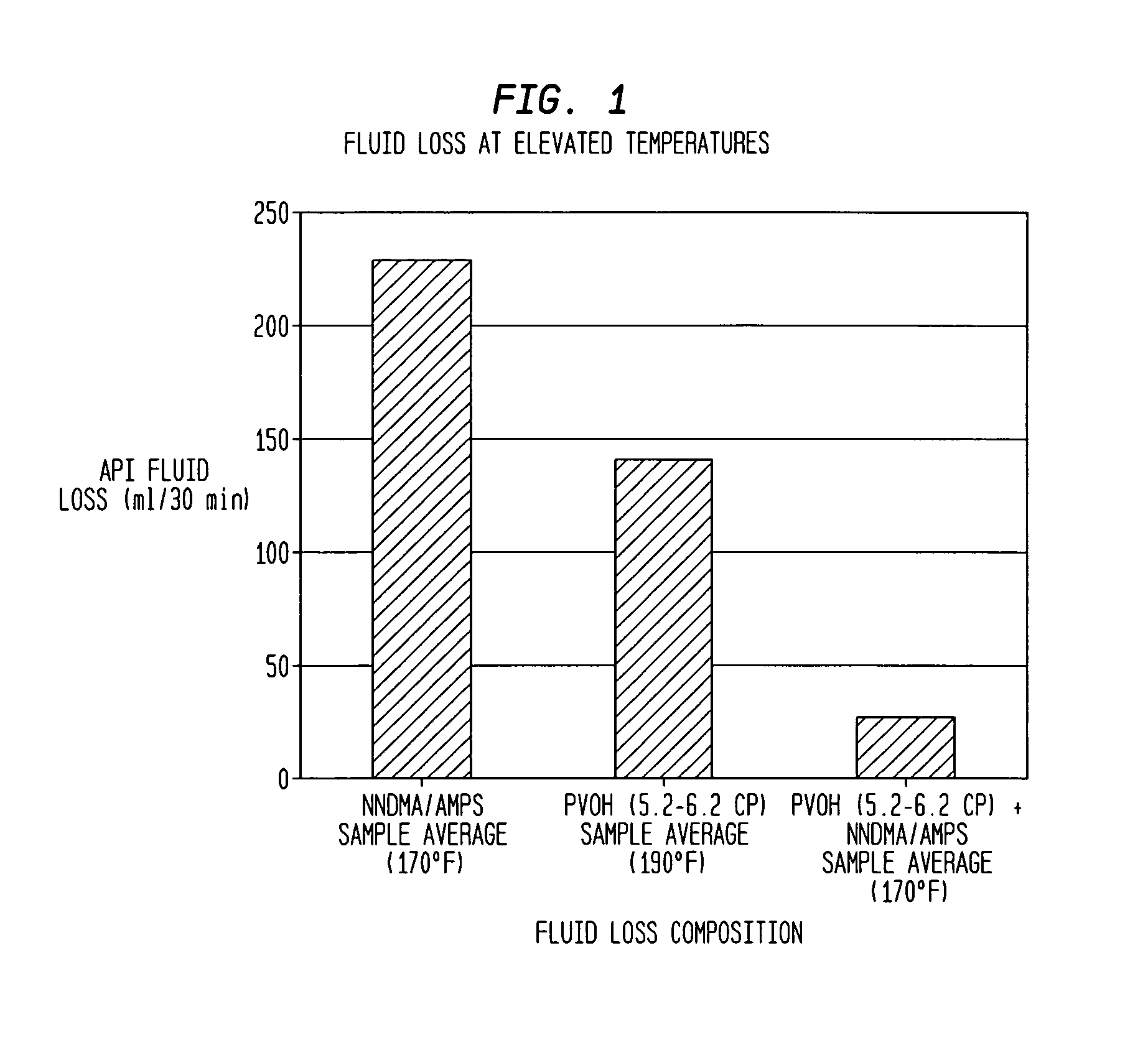
[0027]The slurry of the present invention exhibits a reduced fluid loss over a wide range of temperatures. Preferably the slurry exhibits an API fluid loss of less than about 30 ml / min at 170° F. and 1,000 psi. At 110° F. the slurry typically exhibits an API fluid less than about 25 ml / 30 min, or even less than about 15 ml / 30 min.
[0034]Among desirable features, the invention provides for (1) reduced fluid loss, (2) good rheology—not too hard to stir, anti-settling, lower plastic viscosities, and constant properties so that the cement can be placed and (3) little or no cement set retardation. Additionally, the aqueous concentrate of the present invention provides the following additional benefits: (1) it can be stored in an off-shore platform and mixed with cement powder on demand, (2) it eliminates the need for blending equipment on the rig, and (3) it reduces costs as compared to cellulose polymer aqueous concentrates. The various combined components provide synergy for one another as is seen in reducing the inventory required for effectively controlling operations.

Problems solved by technology

A common problem in petroleum well cementing is the flow of liquid from the cement slurry into porous earth formations in contact with the cement.
This fluid loss is undesirable since it can result in dehydration of the cement slurry, and it causes thick filter cakes of cement solids which can plug the well bore; moreover the fluid lost can damage sensitive formations.
Cement fluid loss is particularly a problem in the process known as squeeze cementing.
Cellulosic polymers are sometimes provided as liquid additives; however, these systems have several drawbacks.
Moreover, cellulosics tend to retard the set time of the cement and increase viscosity of the slurry.
Another drawback of cellulosics is that they tend to thin as they move down hole, causing solids to settle.
Cellulosic additives are also thought more expensive than necessary for wells operating at less than about 65° C. or so.
This method is practical, but not preferred, as the salt or mineral oil may adversely affect the cement properties if not sufficiently diluted or washed away.
High molecular weight additives are conventionally believed superior; however, such additives are not generally amenable to being provided in concentrated solution because viscosity becomes too high.
This leads to large inventory requirements and high shipping costs per pound of additive since mostly water is being handled.
Alternatively, additives are provided in solid form, typically mixed with a dry cement composition which makes it difficult to adjust characteristics of the composition quickly in response to drilling requirements and leads to unnecessary additive usage and / or inferior performance.
Worse, in cases where only seawater is available, such as offshore drilling installations, the additives tend to have lower solubility in seawater and may mix poorly with a seawater cement slurry.

Method used


Image

  • Fluid loss concentrate for hydraulic cement
  • Fluid loss concentrate for hydraulic cement
  • Fluid loss concentrate for hydraulic cement

Examples


examples 1-4

[0082]For purposes of comparison, aqueous cement slurries were prepared using PVOH resin believed to have a characteristic viscosity of about 50 in a ratio of 1:2 with Lomar® D dispersant and tested for fluid loss as indicated in Table 2 below. The slurries had an initial density of about 16.4 lb / gallon.

[0083]As shown below in Table 2, below, the relatively high molecular weight resin, when used with a significant amount of dispersant, exhibits API fluid loss values of about 20 ml / 30 minutes at 110° F.

[0084]

TABLE 2Examples 1-4Fluid LossTempPVOHDispersant (%Fluid LossAPIExample(° F.)(% bwoc)bwoc)(ml / min)(ml / 30 min)11100.51.010 / 30 2021900.5— 38 / 0.4658 (calc)31900.51.016 / 30 3242600.51.089 / 12281 (calc)

examples 5-10

[0085]The following examples illustrate the fluid loss properties of PVOH having various characteristic viscosities.

example 5

[0086]A quantity of 81.2 parts by weight of water was added to a mixing vessel and 18.8 parts by weight of 87-89% hydrolyzed polyvinyl alcohol powder with a characteristic viscosity of 5.2-6.2 cP was added. The mixture was heated to 85 degrees C. for sixty minutes to produce a solution of polyvinyl alcohol. From this solution 1.0% bwoc of the polyvinyl alcohol was mixed with 0.5% bwoc dispersant powder and water with the balance Class H cement to produce a cement slurry with a density of 16.2 pounds per gallon (ppg). The cement slurry was conditioned per American Petroleum Institute (API) standards for 20 minutes and placed in an HTHP Fluid Loss Cell. Fluid loss was measured at a temperature of 110 degrees F. and a pressure of 1000 psig for 30 minutes and the slurry was checked for plastic viscosity and yield point. The slurry exhibited an API Fluid Loss of 13 mL / 30 minutes. The plastic viscosity was 81 cP and the yield point was −2 lb / 100 sq.ft.


PUM

PropertyMeasurementUnit
temperaturesaaaaaaaaaa
weight percentaaaaaaaaaa

Abstract

A fluid loss additive for hydraulic cement, comprising a polyvinyl alcohol resin and a fluid loss ameliorating sulfonic acid-functionalized co-resin, where the polyvinyl alcohol has a characteristic viscosity in the range of about 1 to about 25 cps. The invention includes, in some embodiments, an aqueous concentrate of the PVOH resin and the sulfonic acid-functionalized co-resin, where the total resin content is in the range of about 10% to about 40% and the viscosity is less than 15,000 cps. By way of the invention it is possible to adjust hydraulic cement slurry characteristics in real time upon demand and reduce inventory by providing a concentrated aqueous fluid loss additive.

Description

PRIORITY CLAIM[0001]This application is based upon U.S. Provisional Application Ser. No. 60 / 603,206, filed Aug. 20, 2004, and U.S. Provisional Application No. 60 / 628,383, filed Nov. 16, 2004, both entitled “Method of Formulating Cement for Well Casings and Compositions Therefor,” the priorities of which are hereby claimed.TECHNICAL FIELD[0002]The present invention relates generally to formulating cement with fluid loss additives. These types of cement compositions are used to secure a casing string in a wellbore, for example, in connection with petroleum production. Specifically provided are fluid loss additives comprising relatively low molecular weight polyvinyl alcohol resins with a sulfonic acid co-resin.BACKGROUND OF THE INVENTION[0003]Petroleum well cementing involves mixing a slurry of cement, water, and other additives and pumping it down through steel casing to critical points in the oil well annulus around the casing or in the open hole below the casing string. The primary...

Claims


Application Information

Patent Timeline
Patent Type & Authority Patents(United States)
IPC IPC(8): C08G63/91C04B24/00C09K23/12C09K23/50C09K23/52
CPCC04B24/161C04B24/2623C04B28/02C04B40/0039C09K8/487C04B20/0076C04B22/0026C04B24/383C04B24/123C04B24/18C04B24/223C04B24/226C09K8/46C04B2103/46C04B2201/10C04B2103/67C04B2103/20C04B2103/408C04B24/26
Inventor GEORGE, MICHAEL E.BECKMAN, KRISTI J.SABINS, FREDDIE LYNSIKORA, CORY J.
Owner SEKISUI SPECIALTY CHEM AMERICA
Learn More