Information recording and reproducing apparatus

a technology which is applied in the field of information recording and reproducing apparatus, can solve the problems that the new information recording medium using such a new recording material has not been realized, and achieve the effect of suppressing the movement of an oxygen ion and stabilizing the tunnel structur

Inactive Publication Date: 2010-11-23
KK TOSHIBA
View PDF11 Cites 2 Cited by
  • Summary
  • Abstract
  • Description
  • Claims
  • Application Information

AI Technical Summary

Benefits of technology

[0119]However, as shown in FIG. 27, even when the movement direction of the A ion is not completely coincident with the direction of the applied electric field, the effects of the invention can be obtained.
[0120]Also, FIG. 27 shows a crystal grain boundary 15. Regardless of whether the movement direction of the A ion and the direction of the applied electric field are consistent or inconsistent, even in the case where such crystal grain boundary 15 exists, the effects of the invention can be obtained.
[0121]Finally, an optimal value of a mixing ratio of the respective atoms is described.
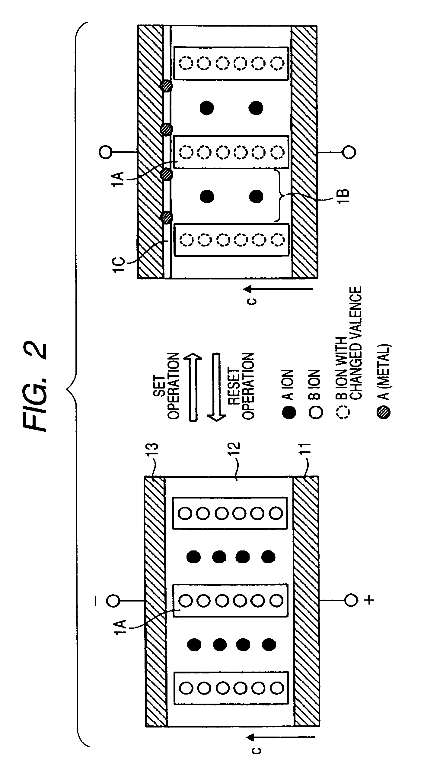
[0122]As explained with reference to FIG. 2, since the structure in which the A ion comes out is able to stably exist, it is possible to optimize a mixing ratio of the A and B ions such that the resistance of each state or a coefficient of diffusion of the A ion becomes an optimal value.
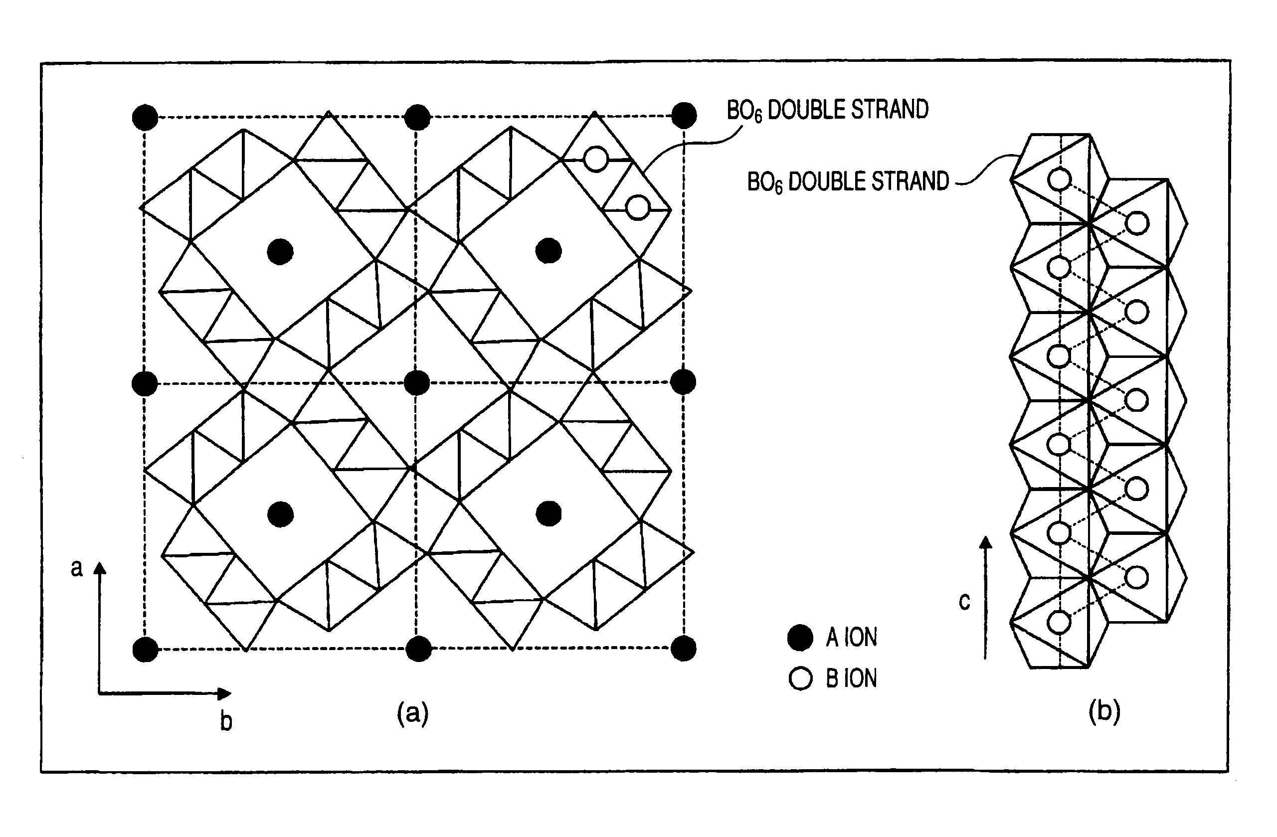
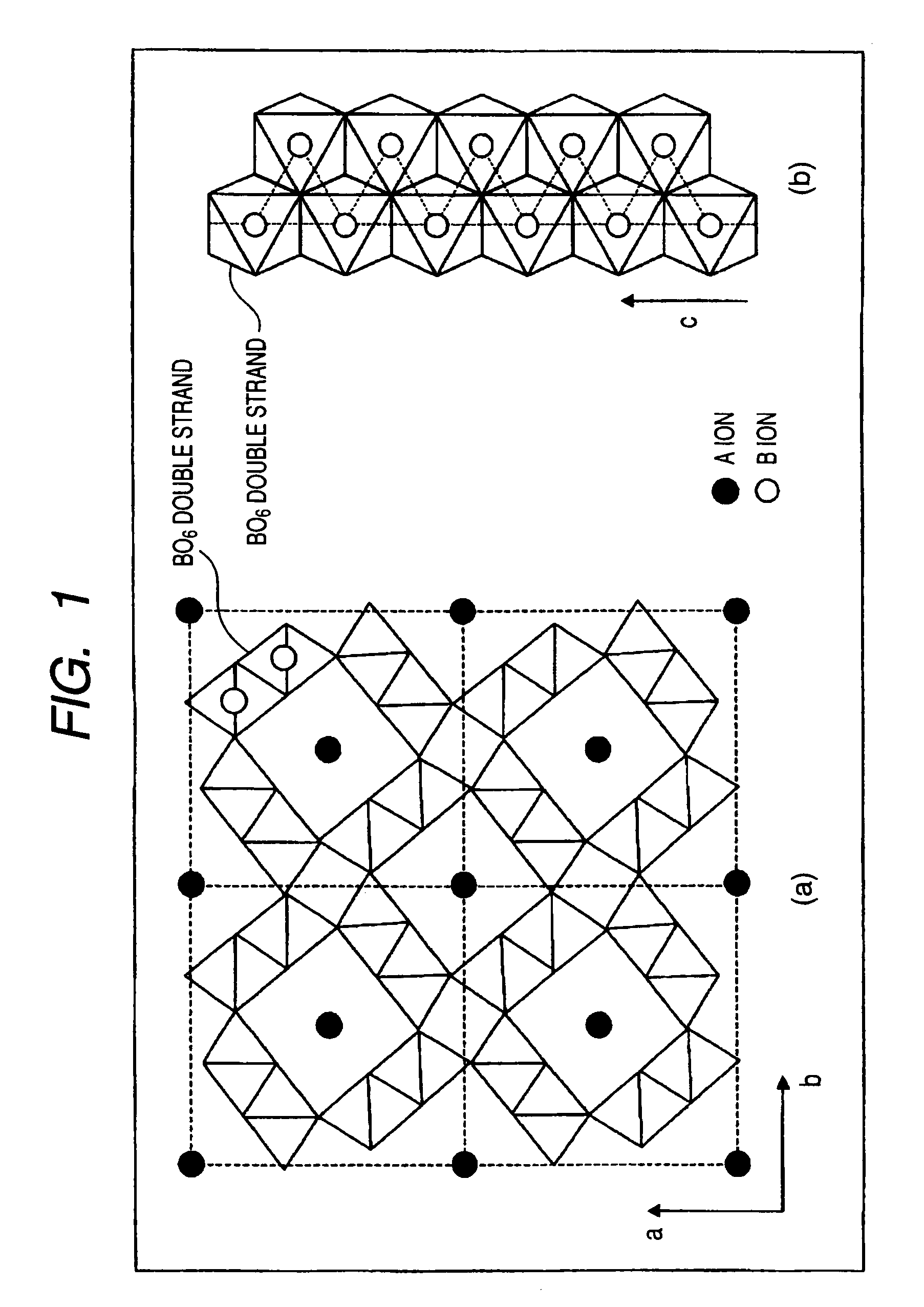
[0123]As to the composition y of the B element, in the tunnel structure in which the A ion entirely comes out (α-MnO2 structure), in the case where an element deficiency does not exist, y is 8.0 (B is tetravalent).
[0124]In the case where the B element is deficient, in order that the tunnel structure may stably exist, it is preferable that the deficiency is up to about 10%, namely, a lower limit of y is about 7.0. Also, in the case where an O (oxygen) element is deficient, it is preferable that the deficiency is up to about 10%, namely, an upper limit of y is about 9.0.

Problems solved by technology

However, a novel information recording medium using such a new recording material has not been realized yet.

Method used


Image

  • Information recording and reproducing apparatus
  • Information recording and reproducing apparatus
  • Information recording and reproducing apparatus

Examples


experimental example

[0211]C. Experimental Example

[0212]A recording medium having the structure as shown in FIG. 7 is used as a sample, and the evaluation is performed by using a pair of probes with an acute tip having a diameter of not more than 10 nm.

[0213]The electrode layer 11 is, for example, a Pt layer formed on a semiconductor substrate. In order to enhance the adhesiveness between a semiconductor substrate and a lower electrode, Ti of about 5 nm may be used as an adhesive layer. The recording layer 12 can be obtained by employing a so-called sol-gel method of coating a sol having adjusted components so as to obtain a desired composition ratio and then baking it, or RF magnetron sputtering using a target having adjusted components so as to obtain a desired composition ratio. Furthermore, for example, diamond-like carbon may be formed as a passivation layer by a CVD method. The thickness of each layer can be designed so as to optimize a resistance ratio between a low resistance state and a high re...


PUM


Abstract

There is proposed a nonvolatile information recording and reproducing device with low power consumption and high thermal stability. The information recording and reproducing apparatus according to an aspect of the present invention includes a recording layer and a unit for recording information by applying a voltage to the recording layer to generate a state change in the recording layer. The recording layer being configured to include at least a first compound having a hollandite structure.

Description

BACKGROUND OF THE INVENTION[0001]1. Field of the Invention[0002]The present invention relates to an information recording and reproducing apparatus with high recording density.[0003]2. Description of the Related Art[0004]In recent years, small-sized portable equipment has been diffused in the world. At the same time, following the great development of high-speed information transport network, demands of small-sized large-capacity nonvolatile memories have rapidly expanded. Above all, in NAND type flash memories and small-sized HDDs (hard disk drives), the recording density has rapidly developed, leading to the formation of a large market.[0005]Under these backgrounds, some ideas of novel memories aiming to greatly exceed the limits of recording density are proposed.[0006]For example, transition metal element-containing ternary oxides such as perovskite and spinel (see, for example, JP-A-2005-317787 and JP-A-2006-80259); binary oxides of a transition metal (see, for example, JP-A-200...

Claims


Application Information

Patent Timeline
Patent Type & Authority Patents(United States)
IPC IPC(8): H01L29/12
CPCB82Y10/00G11B9/149G11C13/0007G11C13/003H01L27/101H01L45/085H01L45/1233H01L45/147H01L45/1608H01L27/2409H01L27/2481G11C2213/31G11C2213/72G11C2213/75G11C2213/79H10B63/20H10B63/84H10N70/245H10N70/8836H10N70/021H10N70/826
Inventor AOKI, SHINYAKUBO, KOHICHITSUKAMOTO, TAKAYUKIKAMATA, CHIKAYOSHIHIRAI, TAKAHIROHIRAOKA, TOSHIRO
Owner KK TOSHIBA
Why Eureka
Try Eureka