Electrical service switching device

a technology of switching device and service lever, which is applied in the direction of circuit-breaking switch, circuit-breaking switch for excess current, protection switch operating/release mechanism, etc., can solve the problems of lack of shape and position stability of the contact lever, movement and tilting between the individual and inability to accurately operate the various levers of the switching mechanism. achieve the effect of high contact shape and position stability

Active Publication Date: 2010-11-23
ABB (SCHWEIZ) AG
View PDF20 Cites 7 Cited by
  • Summary
  • Abstract
  • Description
  • Claims
  • Application Information

AI Technical Summary

Benefits of technology

[0012]A service switching device is disclosed of this generic type which can be manufactured with little effort both manually and fully automatically and, in the process, has high contact shape and position stability.

Problems solved by technology

Manufacturing tolerances during assembly of the board can in this case result in movements and tilting between the individual levers of the switching mechanism.
When the contact lever is struck by the quick release during short-circuit tripping, then it strikes against a stop within the boards, so that the board parts can be moved further away from one another and, over time, the play between the various levers in the switching mechanism can become too great for precise operation.
This can result in a lack of shape and position stability of the contact lever.
Furthermore, the manufacture of the switching mechanism is quite complex, and it is costly to manufacture because of the sensitive tolerances and the riveted joints.
This design is intended to be suitable for completely automatic manufacture that requires high-precision feeding and positioning of a large number of individual parts, thus making the automation production facilities highly complicated and expensive.

Method used


Image

  • Electrical service switching device
  • Electrical service switching device
  • Electrical service switching device

Examples


Embodiment Construction

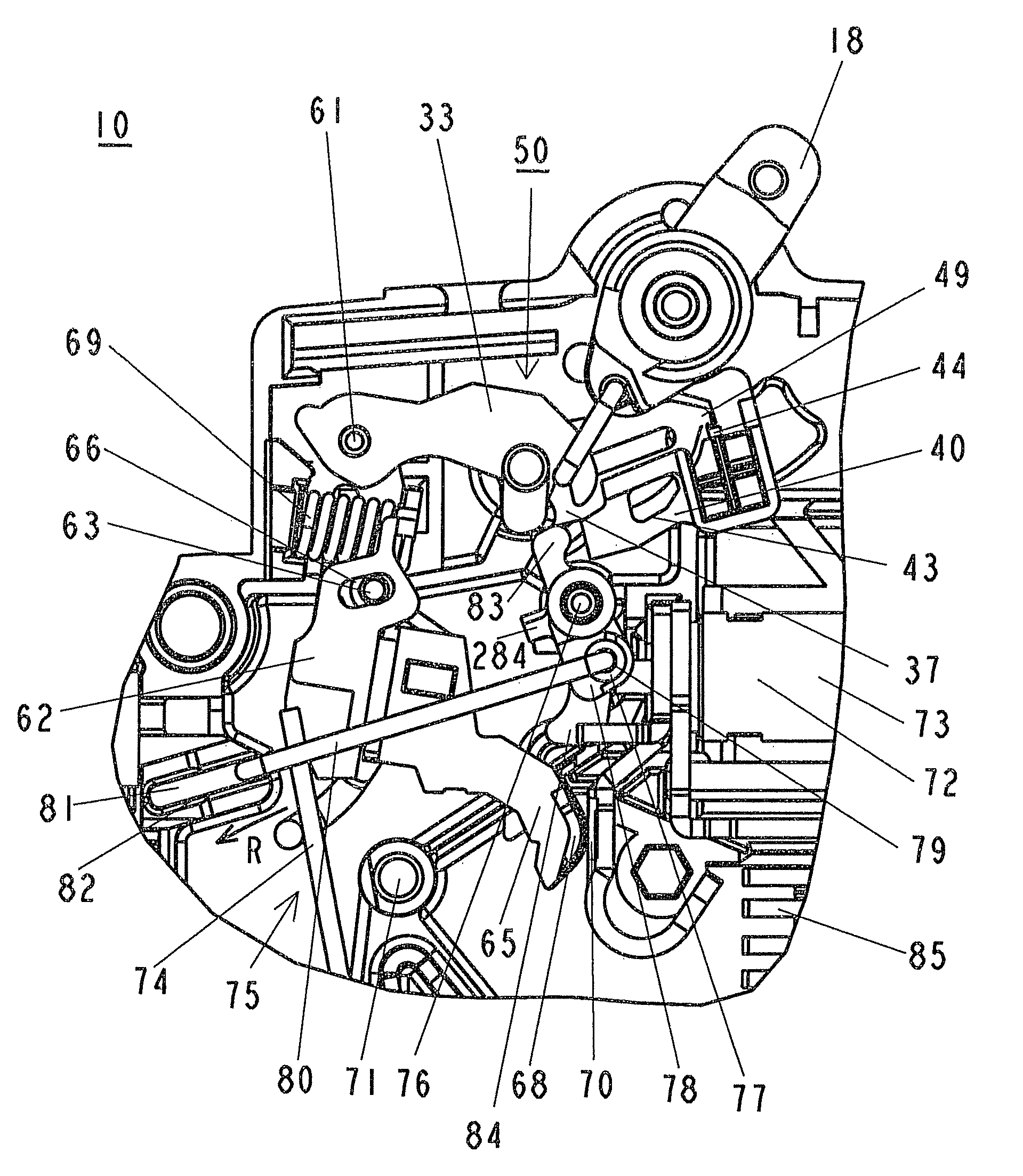
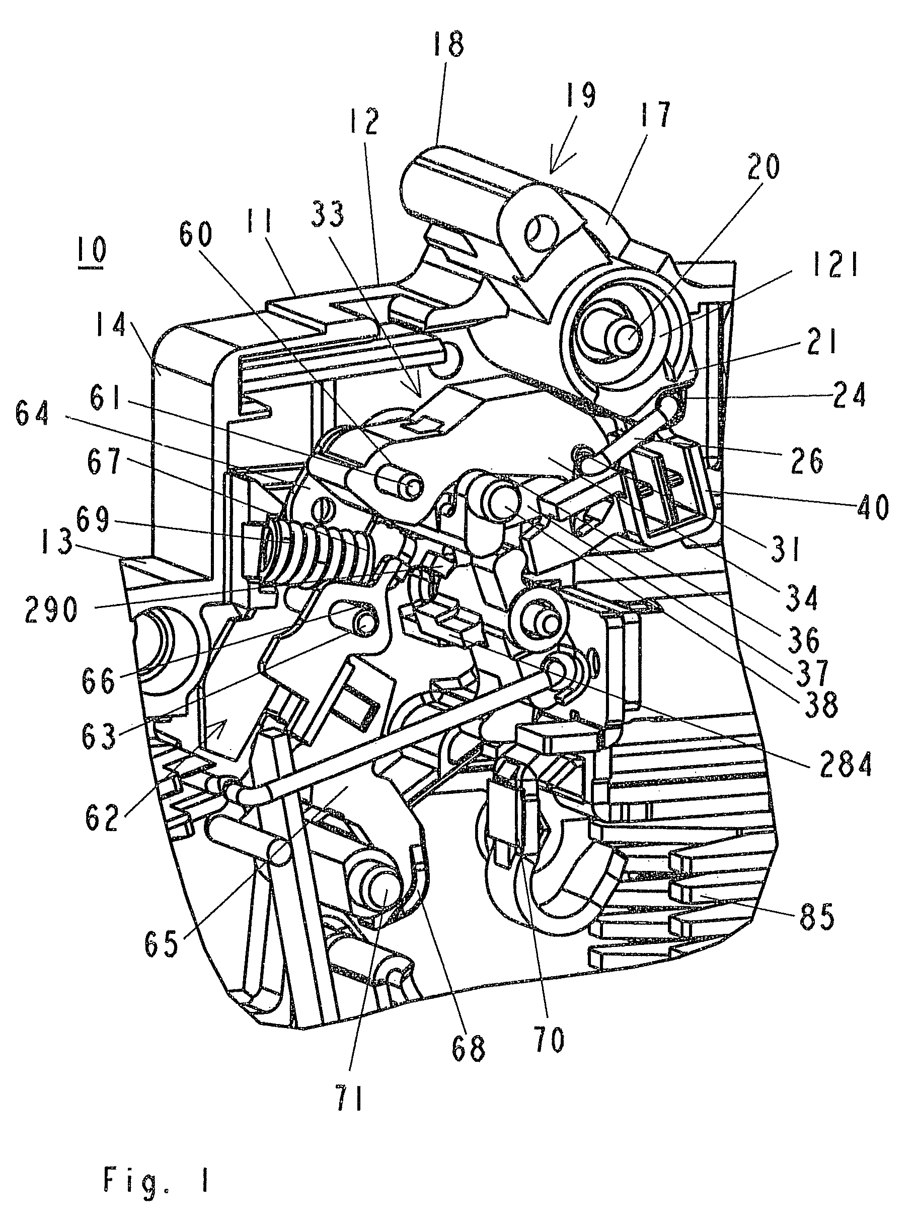
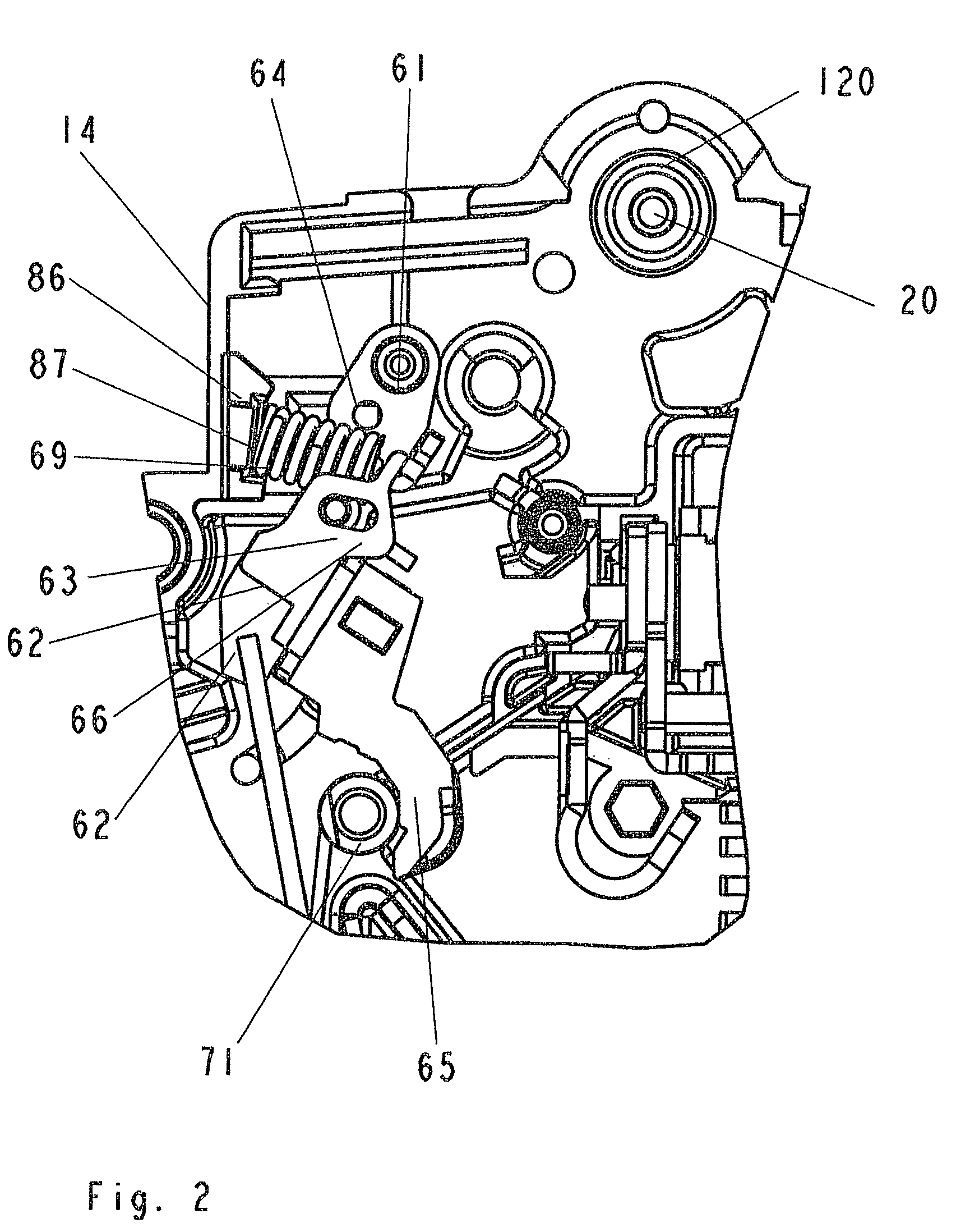
[0023]Thus, according to the disclosure, the contact lever forms a first assembly, which can be inserted in a prefabricated form into the housing of the exemplary service switching device and, after insertion into the housing, is mounted such that it can pivot on a rotation shaft which is connected to the housing at a fixed position, and the switching toggle, together with the tripping lever, the catch lever, the intermediate lever and the clip forms a second assembly, which can be inserted in a prefabricated form into the housing and, after insertion, is connected in an articulated manner at a separation point to the first assembly. The second subject is also referred to in the following text as the joint chain.

[0024]According to one exemplary embodiment of the disclosure, the separation point is formed by a coupling point between a free end of the intermediate lever and a free end of the contact lever. By way of example, the coupling point may in this case be formed by a bolt whic...


PUM


Abstract

The disclosure relates to an electrical service switching device, e.g., a circuit breaker, having a magnetic release with a magnet armature, a thermal release, a fixed and moving contact piece, a switching mechanism which can be tripped by the thermal and magnetic release and has a latching point which is formed by a tripping lever and a catch lever which is mounted in a fixed position such that it can rotate and has an elongated hole in order to guide a clip, wherein the magnet armature can act on the contact lever, to which the moving contact piece is fitted, in order to open the contact point in the event of a short, and the switching mechanism can hold the contact lever permanently in the open position, having a switching toggle for manual operation of the switching mechanism, and having an intermediate lever which is articulated at one of its ends with the contact lever and at its other end on the clip, wherein the clip is articulated with at least one limb on the switching toggle.

Description

RELATED APPLICATIONS[0001]This application claims priority under 35 U.S.C. §119 to German Patent Application No. 10 2007 024 268.0 filed in Germany on May 23, 2007, and German Patent Application No. 10 2008 006 863.2 filed in Germany on Jan. 31, 2008, the entire contents of which are hereby incorporated by reference in their entireties.TECHNICAL FIELD[0002]The disclosure relates to an electrical service switching device, e.g., a circuit breaker.BACKGROUND INFORMATION[0003]A service switching device of this generic type normally has a contact point which is formed by a fixed and a moving contact piece, with the moving contact piece being held on a contact lever which is mounted such that it can pivot. A service switching device of this generic type furthermore has a magnetic release with a magnet armature and a thermal release, as well as a switching mechanism, which can be tripped by the thermal and the magnetic release and has a latching point. This is formed by a tripping lever an...

Claims


Application Information

Patent Timeline
Patent Type & Authority Patents(United States)
IPC IPC(8): H01H81/00H01H75/12H01H83/00H01H77/00
CPCH01H71/526H01H71/40
Inventor WEBER, RALFMUDERS, ERWINEPPE, KLAUS-PETERBECKER, JOACHIM
Owner ABB (SCHWEIZ) AG
Why Eureka
Try Eureka