Multi-beam image forming apparatus configured to perform droop correction

a multi-beam image forming and correction technology, applied in the field of droop correction, can solve the problems of complex configuration, image quality degradation, and correction method requires an extremely high-speed and high-performance calculation unit, and achieve the effects of simple control circuit configuration, reduced density irregularities in scanning, and suppression of image quality degradation

Inactive Publication Date: 2010-11-23
RICOH KK
View PDF10 Cites 0 Cited by
  • Summary
  • Abstract
  • Description
  • Claims
  • Application Information

AI Technical Summary

Benefits of technology

[0017]According to an embodiment of the present invention, the printing ratios of the semiconductor laser elements for each of the printing areas during image formation are counted, and variations in the light amounts due to heat at the emission of the semiconductor laser elements are corrected with predetermined correction coefficients in accordance with the data of the printing ratios. In this manner, the emission light amounts of the semiconductor laser elements during the image formation are controlled. Therefore, it is possible to reduce density irregularities in scanning to suppress degradation in image quality. In addition, it is possible to correct the light amounts at high speed with a simple control circuit configuration.

Problems solved by technology

Among the above methods, the method in which the plural lasers are optically synthesized together causes a complex configuration due to accuracy in scanning positions and further generation of multi beams.
Therefore, the variation in the light amount ΔP is generated between scanning start and finish points, which results in degradation in image quality due to density irregularities.
However, this correction method requires an extremely high-speed and high-performance calculation unit because it performs a calculation in which a correction signal is generated for every pixel.
Therefore, the above method is not necessarily practical from the viewpoint of cost performance.
Besides the continuous light emission, the accumulation of the light emission time leads to the accumulation of heat even when the emission / extinguishment of light is repeatedly performed.
Therefore, when the dots are printed at a region (a), it is not possible to perform printing with a predetermined light amount, and as a result, printed dots would become less dense.
As a result, density irregularities are caused at the dots due to a difference in density between the dots after the continuous light emission is performed at the solid printing region and the dots next to a non-printing region, which in turn causes degradation in image quality.

Method used


Image

  • Multi-beam image forming apparatus configured to perform droop correction
  • Multi-beam image forming apparatus configured to perform droop correction
  • Multi-beam image forming apparatus configured to perform droop correction

Examples


embodiment

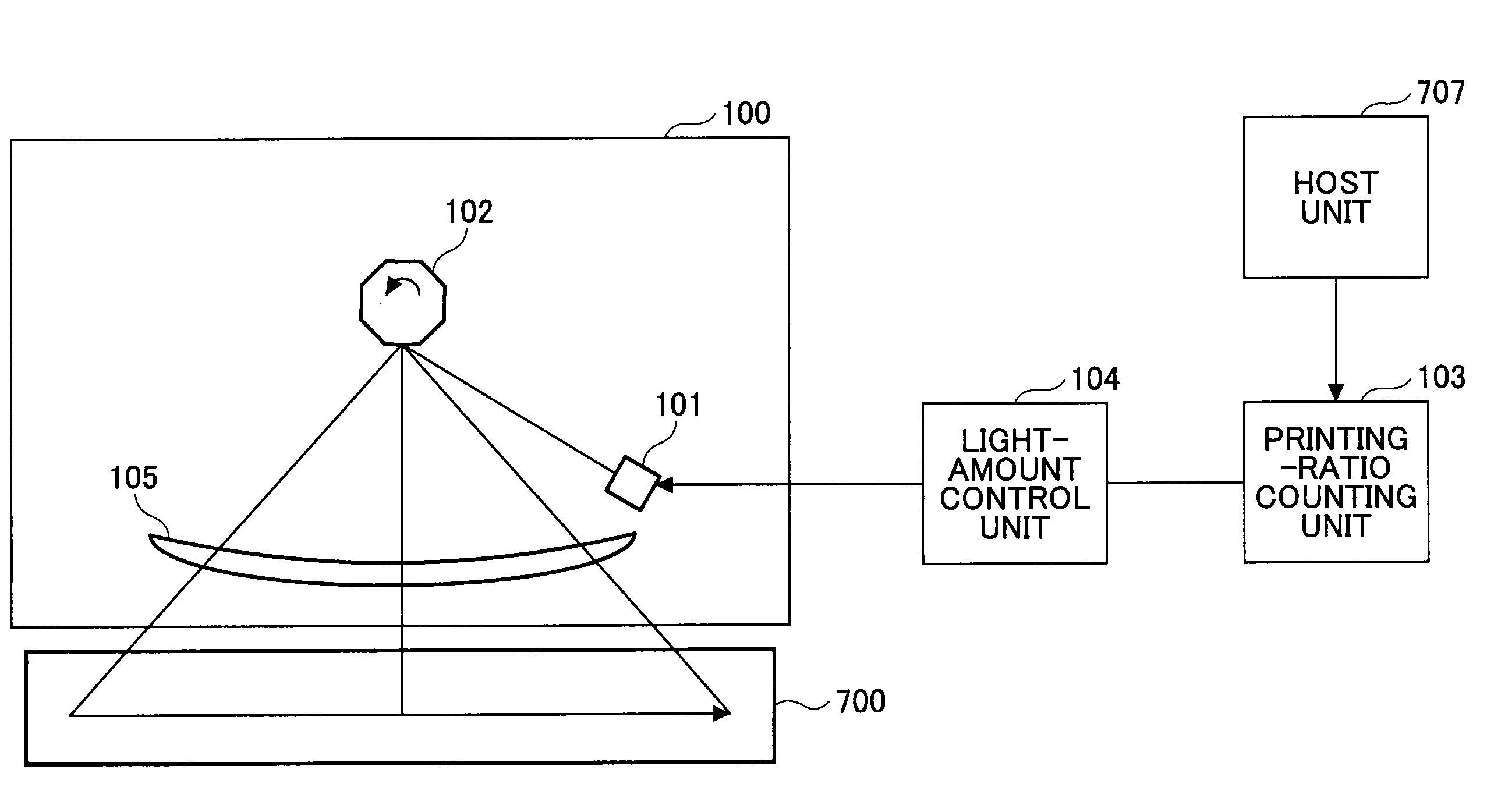
[0029]The embodiment of the present invention is described based on FIGS. 1 and 5 through 9. FIG. 5 shows a schematic block diagram showing the embodiment of the present invention. The embodiment includes an optical scanning unit 100 composed of an optical beam generation unit 101 and a scanning unit 102, a printing ratio counting unit 103, and a light amount control unit 104. Plural laser beams generated from the optical beam generation unit 101 are applied to the deflecting reflection surfaces of the scanning unit 102, such as a polygon mirror, and then caused to pass through an image forming unit such as an f-θ lens 105 to form an image on the photosensitive drum 700. In this manner, the surface of the photosensitive drum 700 is scanned.

[0030]In this embodiment, the optical beam generation unit 101 uses a 20-element semiconductor laser array in which 20 semiconductor laser elements are one-dimensionally arranged to generate 20 laser beams.

[0031]As described above, the droop depen...


PUM


Abstract

A multi-beam image forming apparatus is disclosed in which a semiconductor laser array including plural semiconductor laser elements serves as an optical beam generation unit. The apparatus includes a printing ratio counting unit that counts printing ratios of the semiconductor laser elements in plural printing areas divided in a scanning direction based on image data transmitted from a host unit; and a light amount control unit that controls emission light amounts of the semiconductor laser elements based on a result from the printing ratio counting unit. The light amount control unit calculates droop correction values corresponding to the printing areas from the printing ratios of the semiconductor laser elements based on the printing ratios in the printing areas counted by the printing ratio counting unit so as to correct the light amounts of the semiconductor laser elements.

Description

BACKGROUND OF THE INVENTION[0001]1. Field of the Invention[0002]The present invention relates to droop correction for laser elements generated during image formation in a multi-beam image forming apparatus that forms images using plural semiconductor laser elements serving as an optical beam generation unit.[0003]2. Description of the Related Art[0004]In electrophotographic apparatuses such as laser printers and digital copiers, electrostatic latent images corresponding to recording information are formed by an optical beam generation unit using laser beams after a photoconductive drum is uniformly charged. Then, the electrostatic latent images are developed with toner and transferred onto a sheet by a transfer unit and further fixed so as to form images.[0005]FIG. 1 shows the schematic configuration of a multi-beam image forming apparatus. A photosensitive drum 700, on which a toner image is to be formed, is uniformly charged by a charging unit 701 and then exposed to a laser beam ...

Claims


Application Information

Patent Timeline
Patent Type & Authority Patents(United States)
IPC IPC(8): B41J2/435
CPCG03G15/043G03G15/04072G03G2215/0404G03G15/0435
Inventor ONO, KATSUHIRO
Owner RICOH KK
Why Eureka
Try Eureka