Restricting state diagrams with a set of predefined requirements to restrict a state diagram to a state diagram of a moore or mealy machine

a state diagram and predefined requirement technology, applied in the field of state diagrams, can solve the problems of increasing the complexity and size of the finite state machine, insufficient environment for notifying users, and large burden on users, so as to reduce the burden on users, reduce the time spent debugging, and quickly identify errors

Active Publication Date: 2010-11-23
THE MATHWORKS INC
View PDF3 Cites 25 Cited by
  • Summary
  • Abstract
  • Description
  • Claims
  • Application Information

AI Technical Summary

Benefits of technology

[0005]To address the above described limitations of conventional systems, the present invention provides a user of a state diagramming environment with the ability to specify if the user wants to develop a Moore machine or a Mealy machine. To achieve this, a set of predefined requirements is provided that restricts the state diagram semantics to either semantics of a Moore or Mealy machine. The set of requirements are used to enforce the semantics of the Moore or Mealy machine depending on which machine the user desires. When a user provides a state diagram that does not conform to the set of requirements, the state diagram is identified as non-conforming and the user is notified of the non-conformance. The user is given information describing what aspects of the state diagram do not conform, thereby allowing the user to quickly identify any errors that have been made. As a result of the present invention, the burden placed on the user is reduced and the time spent debugging is minimized.

Problems solved by technology

Currently, environments for developing state diagram representations of finite state machines using Mealy and Moore machines are insufficient for notifying a user when the user does not conform to Moore or Mealy machine semantics.
As a result, a large burden on a user especially with increased complexity and size of the finite state machine.
Debugging these finite state machines requires a substantial amount of the user's time.

Method used


Image

  • Restricting state diagrams with a set of predefined requirements to restrict a state diagram to a state diagram of a moore or mealy machine
  • Restricting state diagrams with a set of predefined requirements to restrict a state diagram to a state diagram of a moore or mealy machine
  • Restricting state diagrams with a set of predefined requirements to restrict a state diagram to a state diagram of a moore or mealy machine

Examples


Embodiment Construction

[0024]Certain embodiments of the present invention are described below. It is, however, expressly noted that the present invention is not limited to these embodiments, but rather the intention is that additions and modifications to what is expressly described herein also are included within the scope of the invention. Moreover, it is to be understood that the features of the various embodiments described herein are not mutually exclusive and can exist in various combinations and permutations, even if such combinations or permutations are not made express herein, without departing from the spirit and scope of the invention.

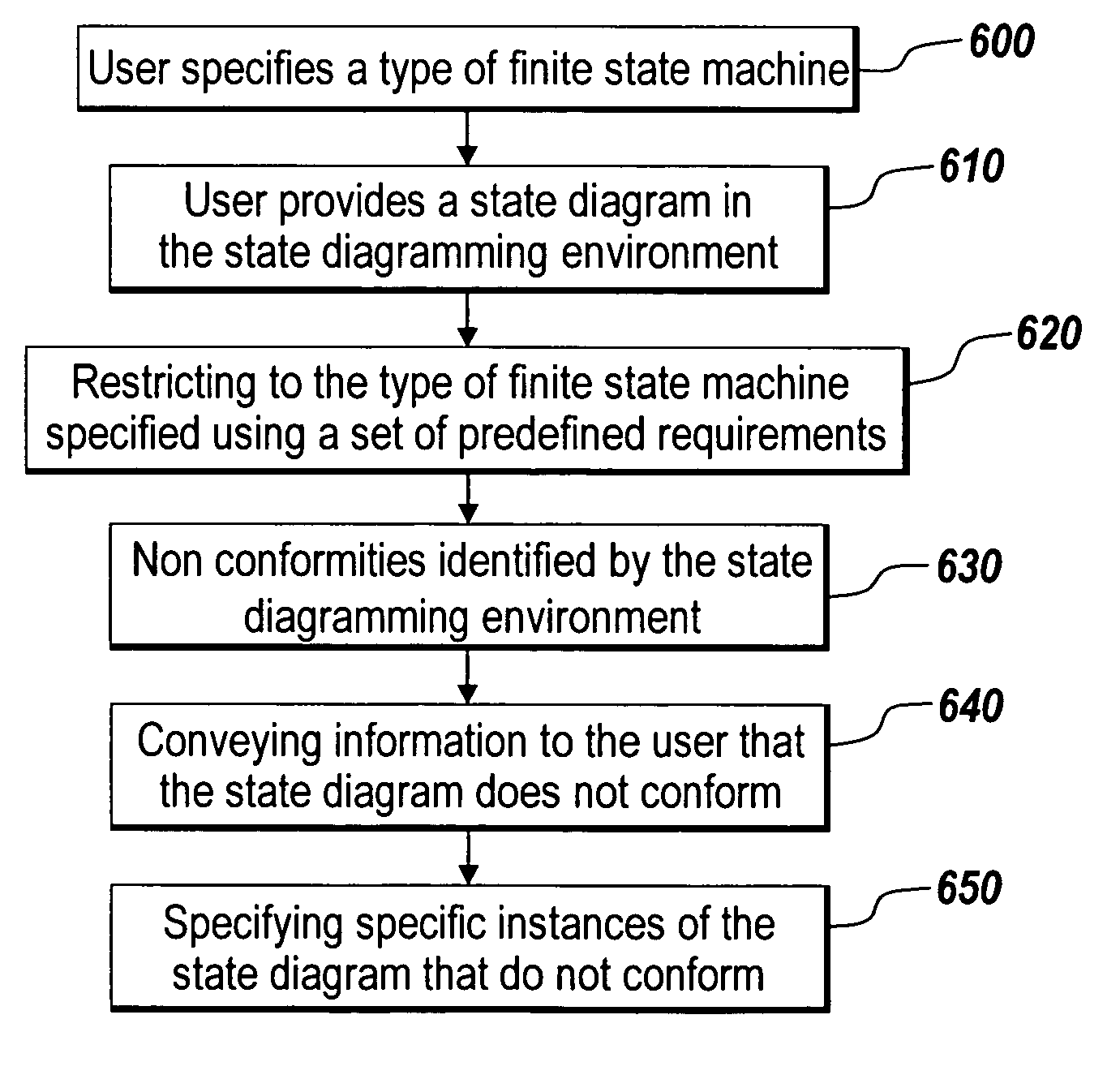
[0025]The illustrative embodiment of the present invention provides a user of a state diagramming environment with the ability to construct either a Moore machine or a Mealy machine using a set of predefined requirements. According to the illustrative embodiment, a desired type of finite state machine may be specified by the user. For example, the user may specify ...


PUM


Abstract

The present invention provides a user of a state diagramming environment with the ability to specify if the user wants to develop a Moore machine or a Mealy machine. To achieve this, a set of predefined requirements is provided that restricts the state diagram semantics to either semantics of a Moore or Mealy machine. When a user provides a state diagram that does not conform to the set of requirements, the state diagram is identified as non-conforming and the user is notified of the non-conformance. The user is given information describing what aspects of the state diagram do not conform, thereby, allowing the user to quickly identify any errors that have been made. As a result of the present invention, the burden placed on the user is reduced and the time spent debugging is minimized.

Description

FIELD OF THE INVENTION[0001]The present invention relates to a state diagram in a state diagramming environment. More specifically, the present invention relates to restricting the state diagram to a Moore or Mealy machine by providing a set of requirements.BACKGROUND[0002]State diagramming environments provide design tools for modeling and simulating event driven systems and subsystems. State diagrams enable the graphical representation of hierarchical and parallel states and the event driven transitions between them. The state diagrams include both logic and internal data. State diagrams can be used to visually detect a current state during the operation of the system being modeled. An example of a state diagramming environment is STATEFLOW from The MathWorks, Inc. of Natick, Mass.[0003]A state diagram may be used to represent finite state machines. Finite state machines may be used to represent event based systems. An example of an event based system may be an electric circuit th...

Claims


Application Information

Patent Timeline
Patent Type & Authority Patents(United States)
IPC IPC(8): G06F17/50
CPCG06F8/10G06F8/34G06F8/35G06F17/5045G06F30/30
Inventor AGRAWAL, ADITYAZHAO, ZHIHONGCOCKERHAM, BETHRAGHAVAN, VIJAY
Owner THE MATHWORKS INC
Why Eureka
Try Eureka