Dual-deflector riding blower

a blower and dual-deflector technology, applied in the direction of cleaning equipment, turf growing, plant cultivation, etc., can solve the problems of compromising maneuverability, burdening manual operation, and not providing the degree of maneuverability required along the perimeter of a yard, so as to achieve the effect of reducing the flow of air

Active Publication Date: 2010-11-30
BRIGGS & STRATTON LLC
View PDF6 Cites 22 Cited by
  • Summary
  • Abstract
  • Description
  • Claims
  • Application Information

AI Technical Summary

Benefits of technology

[0008]In a second embodiment, to a debris mover for moving debris on a surface from a first location to a second location comprises a power source adapted to rotate a shaft, and a blower assembly having an air inlet opening and an air outlet opening and comprising an impeller operatively coupled with the power source. The impeller comprises at least one impeller blade for moving air through the blower when the impeller is rotated by the power source whereby the blower assembly generates a stream of air from the air outlet opening. A safety cage is adapted for coupling with the air inlet opening and comprises a circular wall terminating in a circular lip. When the safety cage is coupled with the air inlet opening, the circular lip is positioned immediately adjacent the at least one impeller blade to define an airflow path from the air inlet opening through the impeller that minimizes the flow of air from between the circular lip and the at least one impeller blade.

Problems solved by technology

While the use of cart-style blowers can be attractive for small areas because of their sharp turning capabilities, their manual operation is burdensome when maintaining large areas.
These vehicle-mounted blower arrangements address the burden of traversing large yard areas, but compromise maneuverability.
They do not provide a degree of maneuverability that is required along the perimeter of a yard.
Further, the vehicle-mounted blowers commonly have the blower unit at the rear of the vehicle, behind the user and out of view during operation.
This is inefficient and unsafe, requiring the user to turn around to watch the blower, rather than facing forward in the direction of travel.
Such a transmission adds cost and weight to the blower, and can result in increased maintenance and repairs.
This can be inefficient and hard on equipment which must be repeatedly shut down and restarted.
Furthermore, many blowers provide a flow of air which is limited to a constant air flow and velocity, and cannot be controlled to accommodate differences in debris type and condition.

Method used


Image

  • Dual-deflector riding blower
  • Dual-deflector riding blower
  • Dual-deflector riding blower

Examples


Embodiment Construction

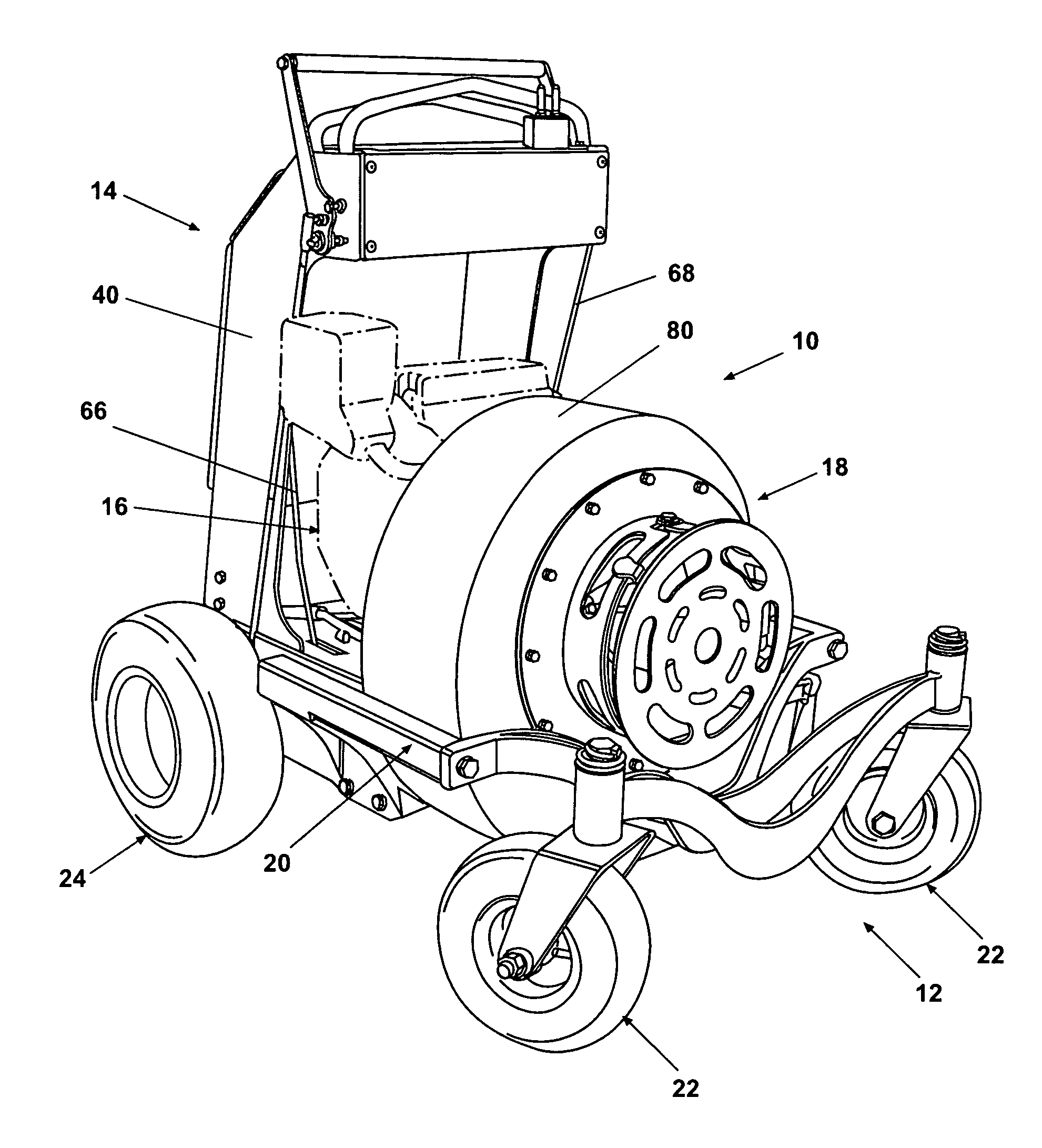
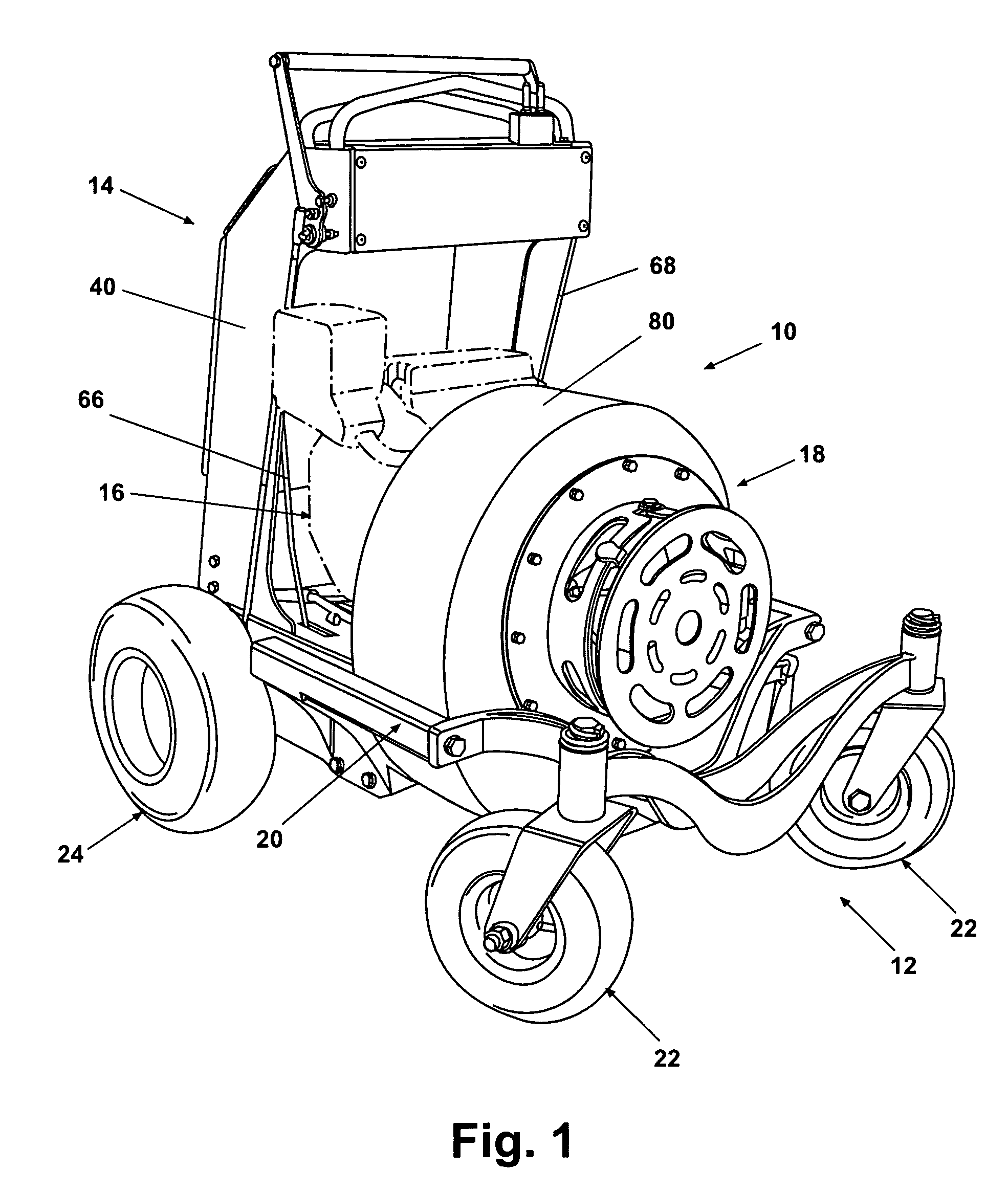
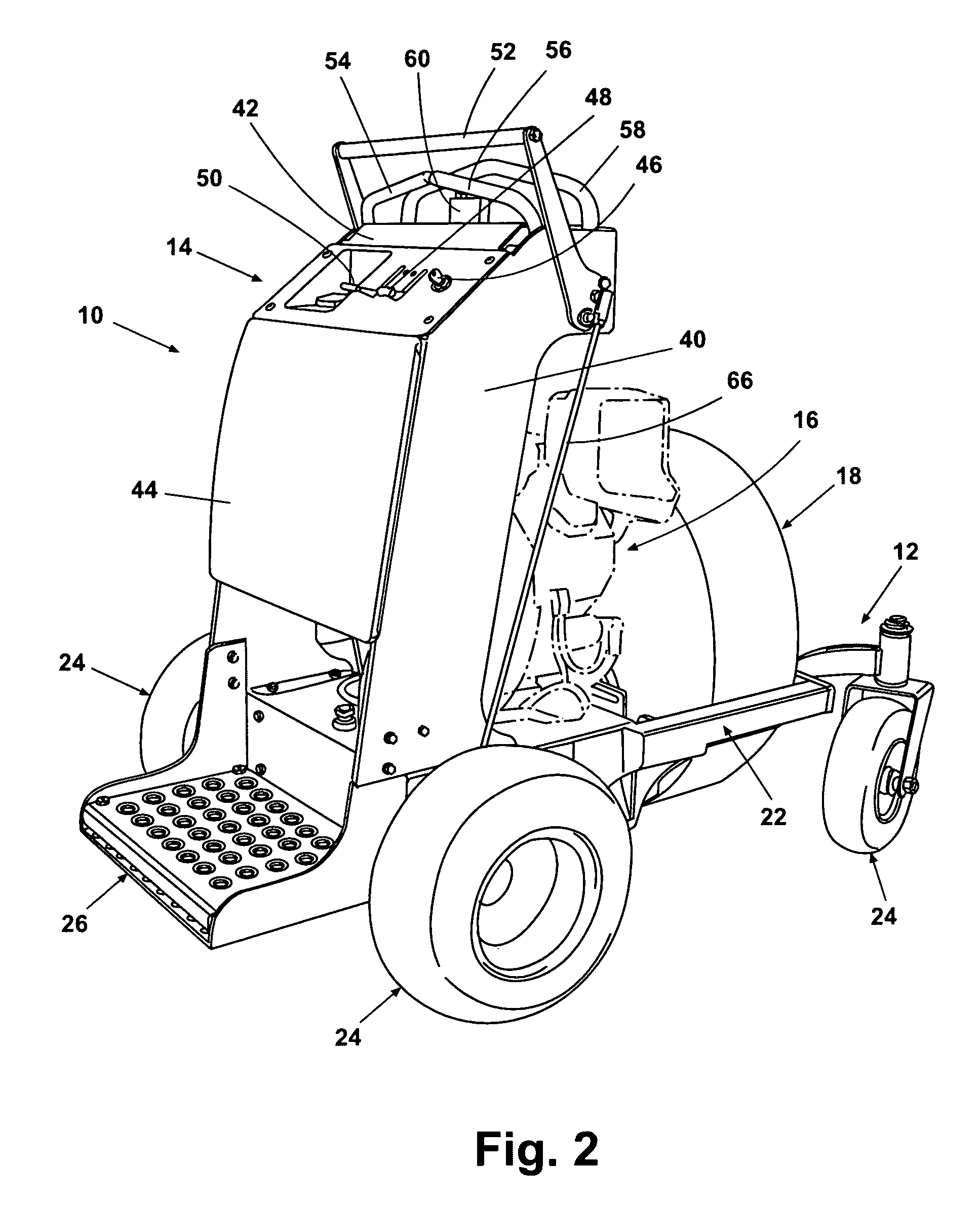
[0028]The invention comprises a riding debris mover which can be used to move debris, such as leaves, twigs, trash, snow, and the like, on a surface such as a lawn or paved area from a first location to a second location. The riding debris mover can move the debris through blowing or vacuuming as selected by an operator. The invention will be generally described with respect to a riding blower, although the debris mover can be coupled to a larger implement, such as a tractor, through a power takeoff assembly, and can be used in a vacuuming mode as hereinafter described.

[0029]A first embodiment of the invention comprising a dual-deflector riding blower 10 is illustrated in FIGS. 1, 2, and 7. The riding blower 10 comprises a suspension assembly 12, a control assembly 14, a power assembly 16, and a blower assembly 18.

[0030]The suspension assembly 12 generally comprises a chassis 196 and a frame 20 coupled to a pair of ground-engaging front wheels 22. The chassis 196 can comprise a port...


PUM


Abstract

A riding debris mover for moving debris on a surface from a first location to a second location comprises a frame coupled to a riding platform adapted to support a user, and a plurality of wheels coupled to the frame comprising at least two opposing traction wheels for driving the riding blower. A power source is coupled to the frame and is operatively coupled with at least the two traction wheels, whereby the traction wheels are rotated independently and the riding blower is propelled. A blower assembly has an air inlet opening and an air outlet opening, the blower assembly being supported by the frame and operatively coupled with the power source, whereby the blower assembly generates a stream of air from the air outlet opening. A deflector assembly is associated with the blower assembly and comprises at least one movable deflector, whereby the at least one movable deflector can be independently moved between an open position, a closed position, and a position intermediate the open position and closed position, to control the air flow and air flow velocity of the stream of air generated by the blower assembly.

Description

BACKGROUND OF THE INVENTION[0001]1. Field of the Invention[0002]The invention relates to yard maintenance equipment and more particularly to a riding air-powered debris mover that is used to clear or collect debris and the like from yards and paved surfaces.[0003]2. Description of the Related Art[0004]Yard maintenance air blowing equipment is commonly known to provide a blower on a hand cart-style frame. These known blowers are operated by a user pushing the cart-style blower unit about the surface to be cleaned. While the use of cart-style blowers can be attractive for small areas because of their sharp turning capabilities, their manual operation is burdensome when maintaining large areas.[0005]Alternatively, it is known to mount centrifugal fan blower units to tractors or other yard vehicles and the like. These vehicle-mounted blower arrangements address the burden of traversing large yard areas, but compromise maneuverability. They do not provide a degree of maneuverability that...

Claims


Application Information

Patent Timeline
Patent Type & Authority Patents(United States)
IPC IPC(8): E01H1/08A47L5/34
CPCA01G1/125A01G20/47
Inventor WEIHL, RICK A.ROBBINS, CHRIS
Owner BRIGGS & STRATTON LLC
Why Eureka
Try Eureka