Integrated compressor/expansion engine

a compressor and expansion device technology, applied in the direction of piston pumps, lighting and heating apparatus, domestic cooling apparatus, etc., can solve the problems of inefficient process, work being done, difficulty in mechanical coupling separate expansion devices, etc., and achieve the effect of retaining compressor compactness and configuration, and saving energy

Inactive Publication Date: 2010-11-30
WHITEMOSS
View PDF16 Cites 1 Cited by
  • Summary
  • Abstract
  • Description
  • Claims
  • Application Information

AI Technical Summary

Benefits of technology

[0013]3. Recover A / C cycle expansion energy.Computer control of these compressor factors allow for broader environmental application, optimum performance, at optimum efficiency. Any improvement in efficiency results in a smaller, more compact, and less expensive system for the same cooling performance (or heating performance for heat pump cycles).
[0018]It is an advantage of the expansion / compression engine to use both compression cylinders and expansion cylinders coupled to one shaft as it provides energy savings over conventional compression engines while retaining compressor compactness and configuration.

Problems solved by technology

This is an inefficient process, producing the desired cooling effect, but with no work being done during the expansion process.
The problem in implementing the system as illustrated in FIG. 2 is the difficulty in mechanically coupling the separate expansion device 22 to the compressor 10.
Further, the work energy recovery is not as hoped for due to the lower operating pressure levels used in typical air conditioning systems.
However, the air conditioning community has now banned fluorocarbons from the environment and is moving rapidly away from the use of low pressure hydrofluorocarbons and to high pressure CO2 gas refrigeration.
The problem of coupling or returning that energy to the compressor system is still unresolved.

Method used


Image

  • Integrated compressor/expansion engine
  • Integrated compressor/expansion engine
  • Integrated compressor/expansion engine

Examples


Embodiment Construction

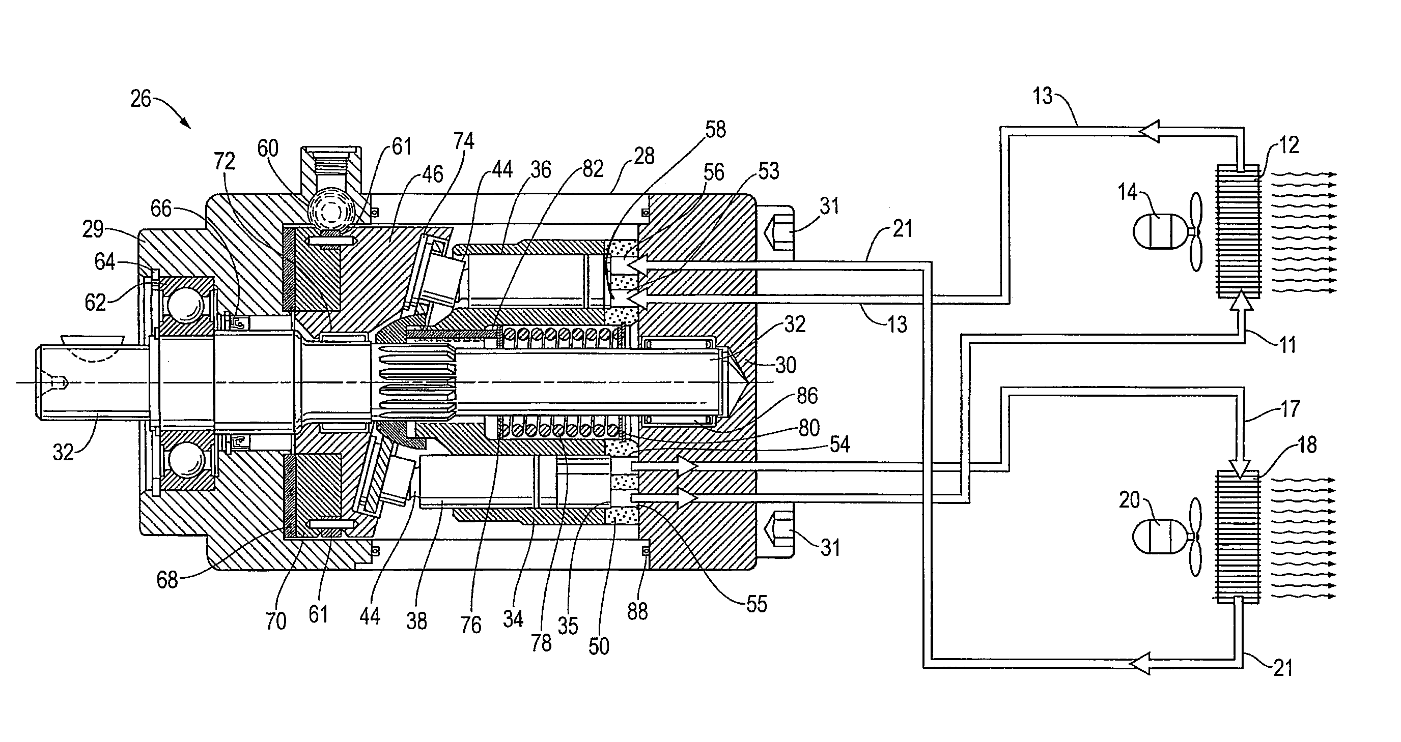
[0029]Turning to FIG. 4, there is illustrated a multi-cylinder axial compression / expansion engine 26 referred to herein as engine 26 of the present design. The engine 26 is contained within a main housing or case 28 having a top or front end 29 and a rear or port end 30. Case bolts 31 extend through the main housing 28 to secure the housing and its components yet allow access to the components when required. A drive shaft 32 spins a cylinder barrel 34 containing at least one expansion cylinder 36 and at least one compression cylinder 38. The cylinder barrel has a head end 35 adjacent to the rear or port end 30. There is a piston foot 44 at one end of each of the pistons opposite the head end 35 with the other end of each piston extending into each of the cylinders 36, 38. The pistons 40, 42 cycle as the cylinder barrel 34 is spun by the drive shaft 32. There is a wedge 46 at the top or front end 29 that causes the pistons 40, 42 to reciprocate as the cylinder barrel 34 is spun. The ...


PUM


Abstract

A multi cylinder compressor / expansion engine having a centrally mounted drive shaft. A cylinder barrel is mounted on the drive shaft and both the cylinder barrel and the drive shaft rotate about a common axis. There is a plurality of cylinders in the cylinder barrel with pistons disposed in each of the cylinders. Some of the cylinders are compression cylinders and some of the cylinders are expansion cylinders. The compression cylinders discharge a fluid at a first high pressure from the engine. The expansion cylinders receive fluid at a second pressure which provides energy to the engine thereby reducing the energy required for the engine to rotate the drive shaft.

Description

CROSS-REFERENCE TO RELATED APPLICATION[0001]This patent application claims priority from U.S. Provisional Application Ser. No. 60 / 708,533 filed on Aug. 15, 2005.I. BACKGROUND AND SUMMARY OF THE INVENTION[0002]This invention relates to a process which utilizes an axial compressor which integrates into itself a compressor and expansion engine.[0003]A schematic diagram of an air conditioning system as known in the prior art is shown in FIG. 1. Air conditioning systems use the process of using a compressor 10 to compress a gas to high pressure 11 which makes it hot. This hot gas 11 is then cooled down in a heat exchanger or condenser 12. Generally a fan 14 forces cool air over or through the heat exchanger 12 to produce a cooled gas 13. The cooled gas 13 then passes through a throttling valve 16 which allows the cooled gas 13 to expand to a low pressure which creates a cold gas 17. The cold gas 17 then passes through another heat exchanger or evaporator 18, where a second fan 20 forces ...

Claims


Application Information

Patent Timeline
Patent Type & Authority Patents(United States)
IPC IPC(8): F25D9/00
CPCF04B27/0808F04B27/0834F04B27/0839F04B27/0895F04B35/00F25B1/02F25B9/06F25B9/008F25B2309/061F25B2400/04F25B2400/076F25B2400/14
Inventor HUGELMAN, RODNEY DALE
Owner WHITEMOSS
Why Eureka
Try Eureka