Planetary gear device

a planetary gear and gearing technology, applied in the direction of gearings, toothed gearings, belts/chains/gearrings, etc., can solve the problem that the above structure is not suited to constituting a flat planetary gear device with reduced thickness

Inactive Publication Date: 2004-03-11
HARMONIC DRIVE SYST IND CO LTD
View PDF8 Cites 7 Cited by
  • Summary
  • Abstract
  • Description
  • Claims
  • Application Information

AI Technical Summary

Problems solved by technology

However, the above structure is not suited to constituting a flat planetary gear device with reduced thickness in the direction of the device axis.

Method used


Image

  • Planetary gear device
  • Planetary gear device
  • Planetary gear device

Examples


first embodiment

[0021] First Embodiment

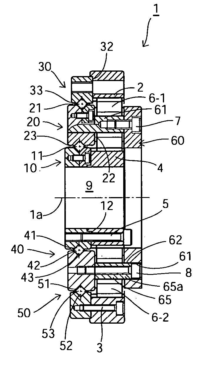
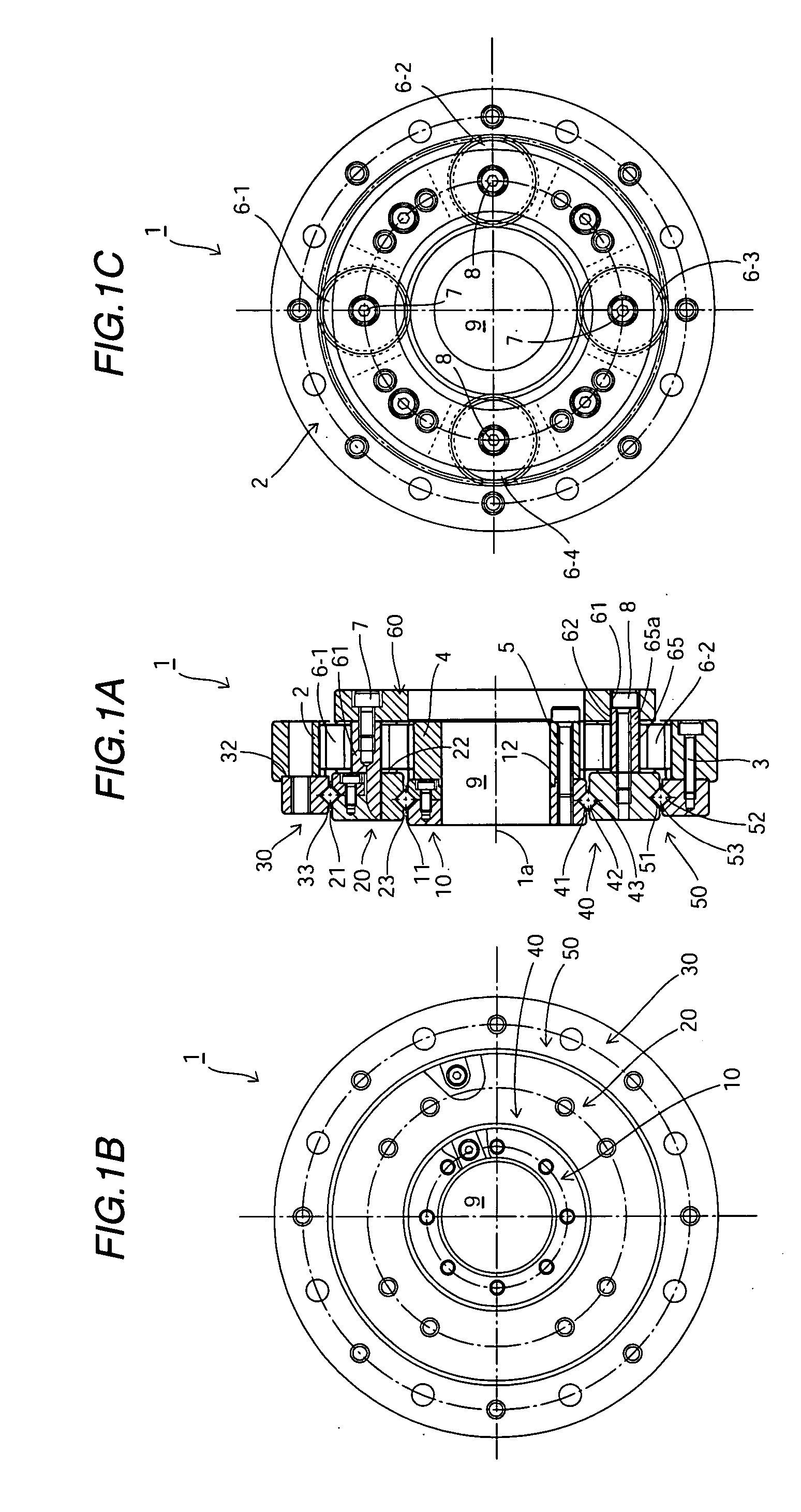
[0022] FIGS. 1A, 1B and 1C are a cross-sectional view, a left end view, and a right end view showing a planetary gear device according to a first embodiment of the present invention. As shown in these drawings, a planetary gear device 1 of the present embodiment includes a first ring-shaped member 10, a second ring-shaped member 20 disposed concentrically around a device axis 1a so as to surround a circular outer circumferential surface 11 of the first ring-shaped member 10, and a third ring-shaped member 30 disposed concentrically so as to surround a circular outer circumferential surface 21 of the second ring-shaped member 20.

[0023] An internal gear 2 is coaxially fastened onto a ring-shaped end surface 32 of the outermost third ring-shaped member 30 by fixing bolts 3. On the same side of the planetary gear device 1, a cylindrical sun gear 4 is also coaxially fastened onto a ring-shaped end surface 12 of the first ring-shaped member 10 by fixing bolts 5. Bet...

second embodiment

[0038] Second Embodiment

[0039] FIGS. 3A, 3B and 3C are a cross-sectional view, a left end view, and a right end view showing a two-stage planetary gear device that is constituted by the planetary gear device 1 of the first embodiment. The two-stage planetary gear device 100 includes a front stage-side planetary gear mechanism 110 and a rear stage-side planetary gear mechanism 120. The rear stage-side planetary gear mechanism 120 has substantially the same construction as the planetary gear device 1 of the first embodiment. Accordingly, the corresponding parts are given the same reference numerals and description thereof will be omitted.

[0040] In the two-stage planetary gear device 100 of the present embodiment, a central rotational shaft 70 (the fifth member) is concentrically disposed rotatably on the inside of a circular inner circumferential surface 13 of the first ring-shaped member 10 in the rear stage planetary gear mechanism 120. This central rotational shaft 70 is composed o...


PUM


Abstract

A planetary gear device (1) includes a first, a second, and a third ring-shaped member (10, 20, 30) that are concentrically arranged in that order from the inside. A sun gear (4) is coaxially fixed to an end surface of the first ring-shaped member (10), planet shafts (61 to 64) of planet gears (6-1 to 6-4) are supported on an end surface of the ring-shaped member (20), and an internal gear (2) is coaxially fixed to an end surface of the third ring-shaped member (30). A first cross roller bearing (40) is formed between the first and second ring-shaped members (10, 20) and a second cross roller bearing (50) is formed between the second and third ring-shaped members (20, 30). Each member is arranged concentrically on a plane that is perpendicular to the device axis (1a), so that an planetary gear device that is extremely slim in the device axial direction can be realized. Since the respective gear parts can be accessed from both sides in the device axial direction, the input and output can be laid out with great freedom.

Description

[0001] The present invention relates to a small, compact planetary gear device and in particular to a planetary gear device with reduced thickness in the device axial direction.RELATED ART[0002] A conventional planetary gear device is composed of a reduction mechanism for reducing the speed of an input high-speed rotation and a bearing for rotatably supporting a reduced-speed rotation output member that outputs the rotation whose speed is reduced by the reduction mechanism. The reduction mechanism and the bearing are disposed coaxially along the device axial direction.[0003] However, the above structure is not suited to constituting a flat planetary gear device with reduced thickness in the direction of the device axis.[0004] It is an object of the present invention to provide a planetary gear device with minimal thickness in the device axial directions.[0005] To achieve the above and other objects, a planetary gear device of the present invention includes: a first member that has a...

Claims


Application Information

Patent Timeline
Patent Type & Authority Applications(United States)
IPC IPC(8): F16H1/28F16H57/08
CPCF16H57/08F16H1/28
Inventor SHIRASAWA, NAOMI
Owner HARMONIC DRIVE SYST IND CO LTD
Why Eureka
Try Eureka