Heat exchanger

a heat exchanger and heat exchanger technology, applied in indirect heat exchangers, lighting and heating apparatus, stationary conduit assemblies, etc., can solve the problems of deterioration of air conditioning feeling, uneven volume of internal fluid, complex structure of inlet tanks, etc., to reduce the volume of internal fluid flowing into the remaining tubes is increased, and the volume of internal fluid flowing into the tubes that are closer to the inlet port

Active Publication Date: 2010-11-30
DENSO CORP
View PDF17 Cites 7 Cited by
  • Summary
  • Abstract
  • Description
  • Claims
  • Application Information

AI Technical Summary

Benefits of technology

[0015]Since the openings of the ends of the predetermined tubes are partly covered by the cover member, the volumes of internal fluid flowing into the predetermined tubes reduce, so that volumes of the internal fluid flowing into the remaining tubes increase. In other words, the volumes of the internal fluid flowing into the tubes that are closer to the inlet port are reduced, and the volumes of the internal fluid flowing into the remaining tubes, which are relatively farther away from the inlet port, are increased. As such, the volume of the internal fluid in each of the tubes is uniform. Also, the volume of the internal fluid in each tube is uniform by simply partly covering the openings of the ends of the predetermined tubes by the cover member.
[0017]Since the openings of the ends of the predetermined tubes are partly covered by the cover member, the volumes of internal fluid flowing into the predetermined tubes reduce, so that volumes of the internal fluid flowing into the remaining tubes increase. In other words, the volumes of the internal fluid flowing into the tubes that are closer to the inlet port are reduced, and the volumes of the internal fluid flowing into the remaining tubes, which are relatively farther away from the inlet port, are increased. As such, the volume of the internal fluid in each of the tubes is uniform.

Problems solved by technology

That is, the volumes of the internal fluid are likely to be uneven between the tubes.
With this, distribution of air temperature downstream of the heat exchanger with respect to a flow of air is uneven, resulting in deterioration of air conditioning feeling.
However, the structure of the inlet tank becomes complex.

Method used


Image

  • Heat exchanger
  • Heat exchanger
  • Heat exchanger

Examples


first embodiment

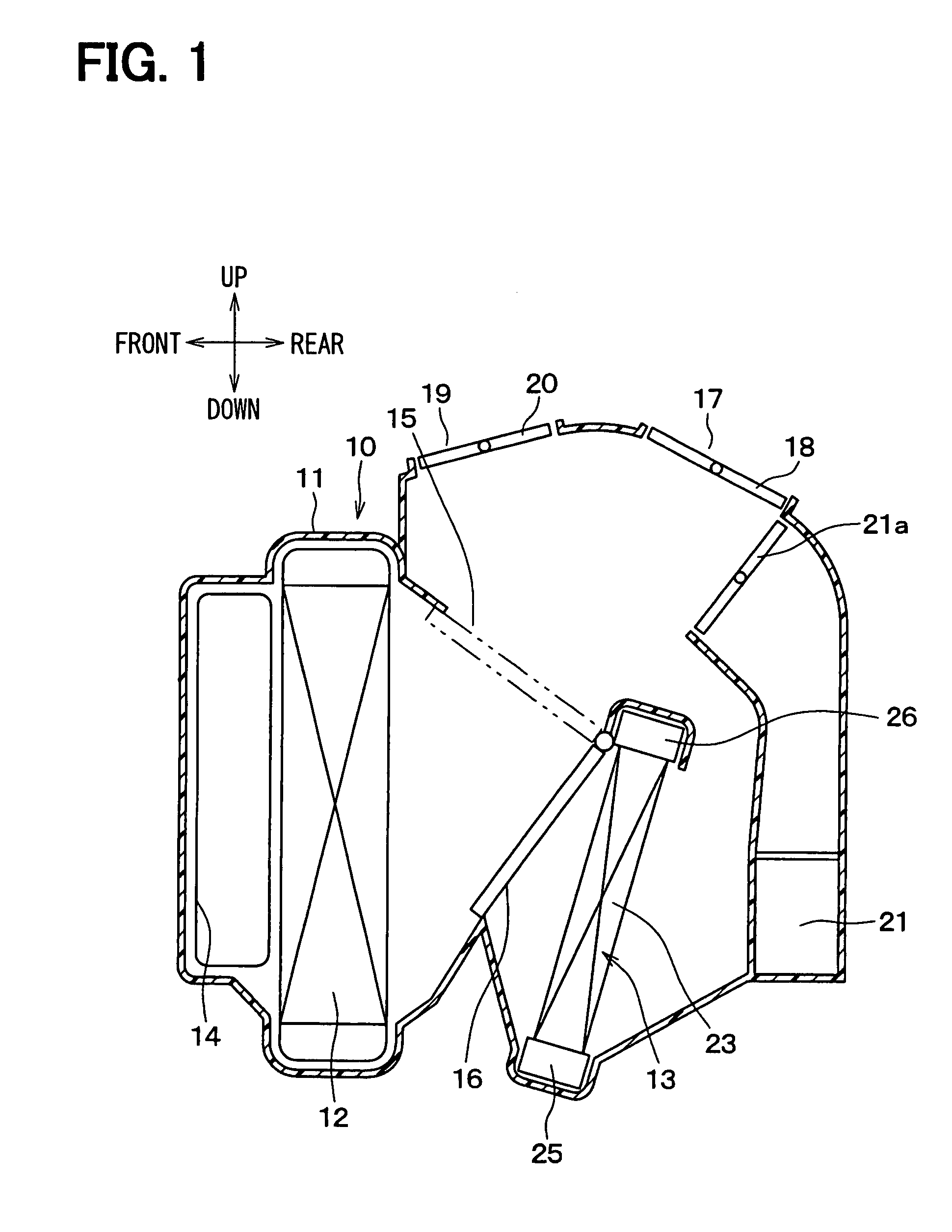
[0042]A first embodiment of the present invention will now be described with reference to FIGS. 1 to 14. FIG. 1 shows an air conditioning unit 10 for a vehicular air conditioning apparatus. In the first embodiment, a heat exchanger is employed as a heating heat exchanger (heater core) 13 of the air conditioning unit 10, for example. In the drawings, an up and down arrow, a front and rear arrow and a left and right arrow denote respective directions when the air conditioning unit 10 is mounted on a vehicle.

[0043]The air conditioning apparatus is mounted in a space defined by an instrument panel at a front part of a passenger compartment of a vehicle. Although not illustrated, the air conditioning apparatus has a blower unit for supplying a flow of air toward the air conditioning unit 10. The air conditioning apparatus is for example arranged in a semi-center layout in the space so that the air conditioning unit 10 is mounted in a substantially middle position with respect to a vehicl...

second embodiment

[0109]A second embodiment will be described with reference to FIGS. 15 to 17. In this embodiment, the plate member 34 is preliminarily fixed to the tank main body 31 before the heater core 13 is integrally brazed.

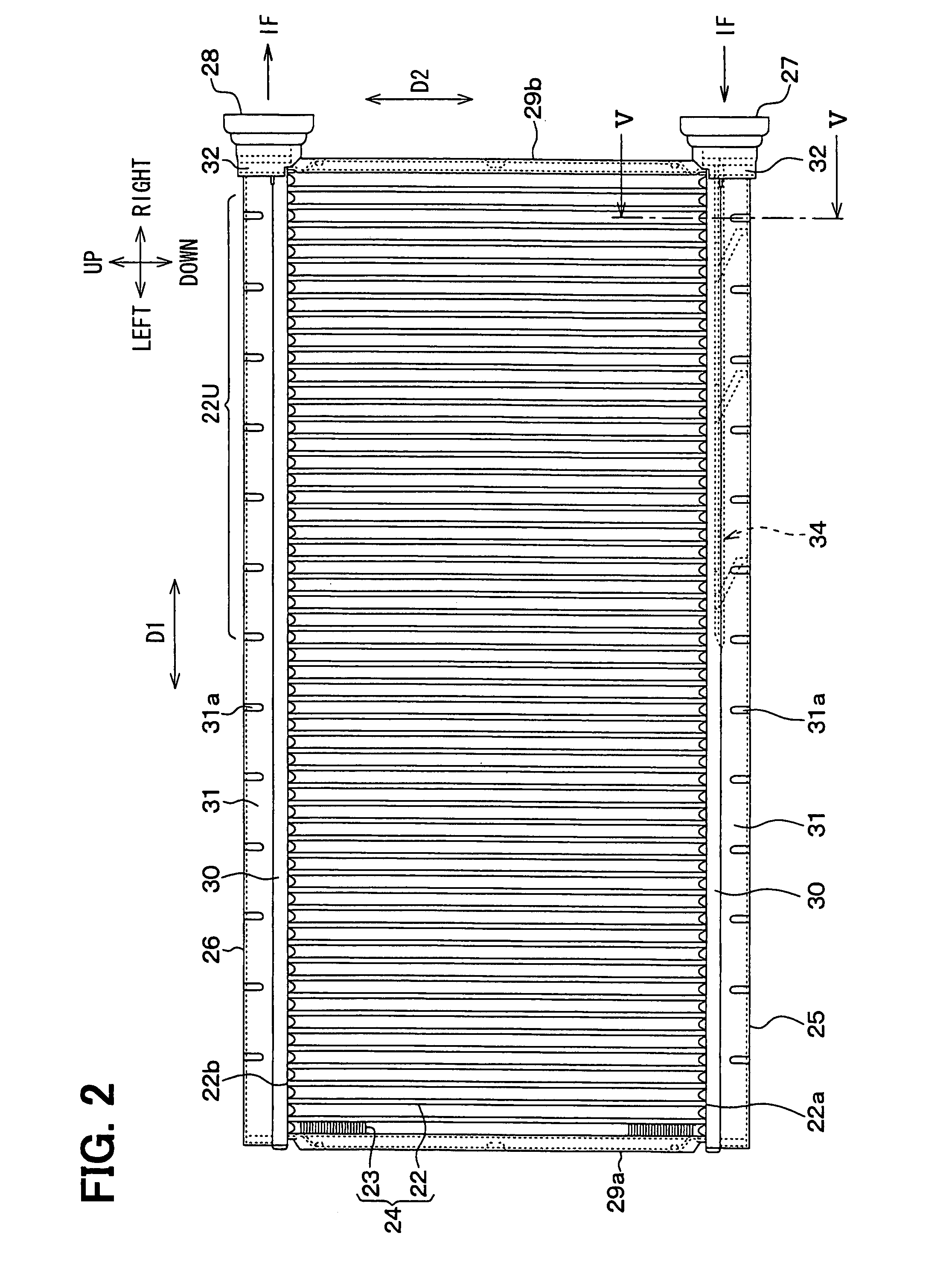
[0110]As shown in FIG. 15, the plate member 34 is formed by shaping a metal plate such as aluminum plate. The plate member 34 has a main wall 40 and leg portions 41 for fixing the main wall 40 to the tank main body 31. The main wall 40 has a generally plate shape and extends in the tube stacking direction D1 with a predetermined width. The wall surface 34a is provided by a first surface of the main wall 40, which faces the inlet ends 22a of the tubes 22U.

[0111]As shown in FIG. 16, the main wall 40 has a tapered shape such that the width thereof reduces from its first end (left end in FIG. 16) that is adjacent to the inlet port 27 toward its second end (right end in FIG. 16) that is farther away than the first end with respect to the inlet port 27. In this embodiment, the ma...

third embodiment

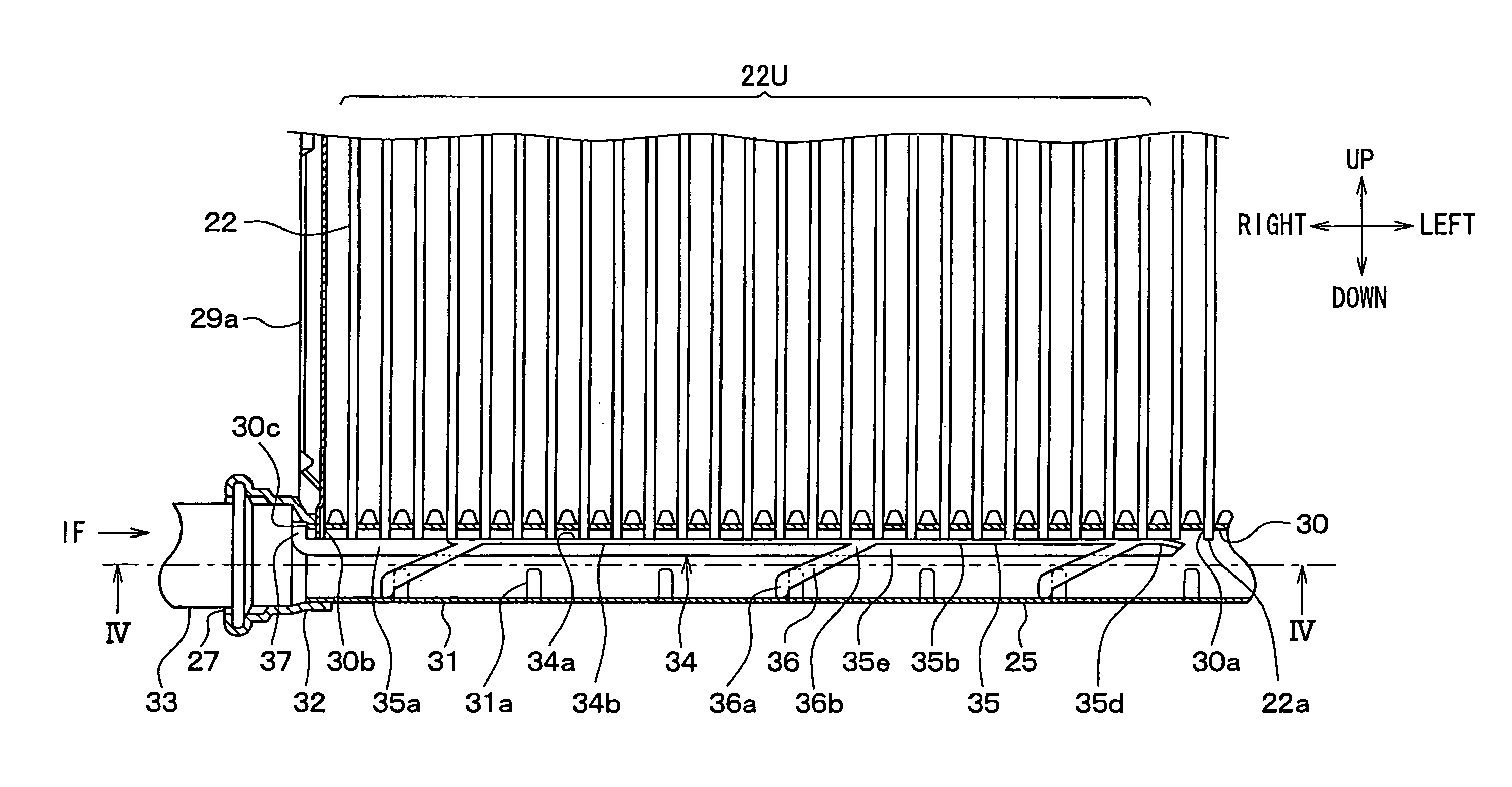
[0120]A third embodiment will be described with reference to FIGS. 18A and 18B. In the third embodiment, the heater core 13 does not have the plate member 34. In place of the plate member 34, the core plate 30 is formed with embossed portions 42 as the cover member.

[0121]The embossed portions 42 project from peripheral portions of the tubes insertion holes 30a, which have burring shapes, toward the inside of the inlet tank 25. Each of the embossed portions 42 has a shape along the inlet end 22a of the tube 22U, which projects inside of the inlet tank 25. The embossed portion 42 partly overlaps the tube insertion hole 30a, as shown in FIG. 18B.

[0122]As such, the opening of the inlet end 22a of each tube 22U is partly covered by the embossed portion 42. Accordingly, similar to the first embodiment, the volume of the internal fluid in each tube 22 is uniform and the difference of the discharge air temperatures in the tube stacking direction D1 is reduced.

[0123]The embossed portions 42 ...


PUM


Abstract

A heat exchanger has tubes, an inlet tank and an outlet tank. The inlet tank and the outlet tank are coupled to ends of the tubes. The inlet tank and the outlet tank have an inlet port and an outlet port, respectively, on ends thereof. The heat exchanger further has a cover member disposed in at least one of the inlet tank and the outlet tank. The cover member partly covers openings of the ends of predetermined tubes of the tubes, the predetermined tubes being closer to at least one of the inlet port and the outlet port.

Description

CROSS REFERENCE TO RELATED APPLICATION[0001]This application is based on Japanese Patent Applications No. 2006-210650 filed on Aug. 2, 2006 and No. 2007-59086 filed on Mar. 8, 2007, the disclosures of which are incorporated herein by reference.FIELD OF THE INVENTION[0002]The present invention relates to a heat exchanger.BACKGROUND OF THE INVENTION[0003]For example, a heat exchanger has a plurality of tubes through which an internal fluid flows, a first tank for distributing the internal fluid into the tubes and a second tank for collecting the internal fluid from the tubes. The inlet tank has an inlet port on its first end and the outlet tank has an outlet port on its first end. The inlet port and the outlet port are disposed on the same side with respect to a tube stacking direction in which the tubes are stacked. Such a heat exchanger is used, for example, as a heating heat exchanger (heater core) for a vehicular air conditioning apparatus.[0004]In the inlet tank of the heat excha...

Claims


Application Information

Patent Timeline
Patent Type & Authority Patents(United States)
IPC IPC(8): F28F9/22
CPCF28D1/05366F28F9/026F28D2021/0084F28D2021/0094F28D2021/0096
Inventor SEKITO, YASUHIROOKUMURA, YOSHIHIKOMURAKI, TOSHIHIKONAKAMURA, MITSUGU
Owner DENSO CORP
Why Eureka
Try Eureka