Trigger sprayer venting apparatus

a technology of trigger sprayer and venting apparatus, which is applied in the direction of single-unit apparatus, liquid transfer device, packaging, etc., can solve the problems of liquid leaking from the liquid container, and achieve the effect of reducing manufacturing cost and easy assembly

Inactive Publication Date: 2007-12-20
CONTINENTALAFA DISPENSING CO
View PDF6 Cites 21 Cited by
  • Summary
  • Abstract
  • Description
  • Claims
  • Application Information

AI Technical Summary

Benefits of technology

[0021] It is desirable that the dip tube used with the trigger sprayer be axially aligned with the connector cap axis so that the dip tube is inserted through the center of the liquid container opening as the trigger sprayer is attached to the liquid container. In order to axially align the dip tube with the center axis of the connector cap, a novel plug seal is assembled to the sprayer housing. One of the unique features of the plug seal is that it enables the attachment of the dip tube to the trigger sprayer at a position that is axially aligned with the connector cap center axis. The plug seal also communicates the dip tube with the liquid inlet opening of the sprayer housing that is not axially aligned with the dip tube. The plug seal also has an inlet valve seat column that is assembled into the liquid supply passage of the sprayer housing. The valve seat column provides a valve seat surface for an inlet valve that controls the flow of liquid through the liquid inlet opening and the liquid supply passage to the pump chamber, and prevents the reverse flow of liquid. The plug seal is also provided with an elongate trough that forms a part of the vent air flow path. The trough extends along a surface of the plug seal in a transverse direction relative to the center axis of the connector cap. The elongate trough has opposite ends, with one end receiving the vent ope

Problems solved by technology

However, providing a flow path for air to enter the liquid container also creates the possibility of liquid leaking from the liquid container through the vent air flow path to the e

Method used


Image

  • Trigger sprayer venting apparatus
  • Trigger sprayer venting apparatus
  • Trigger sprayer venting apparatus

Examples


Embodiment Construction

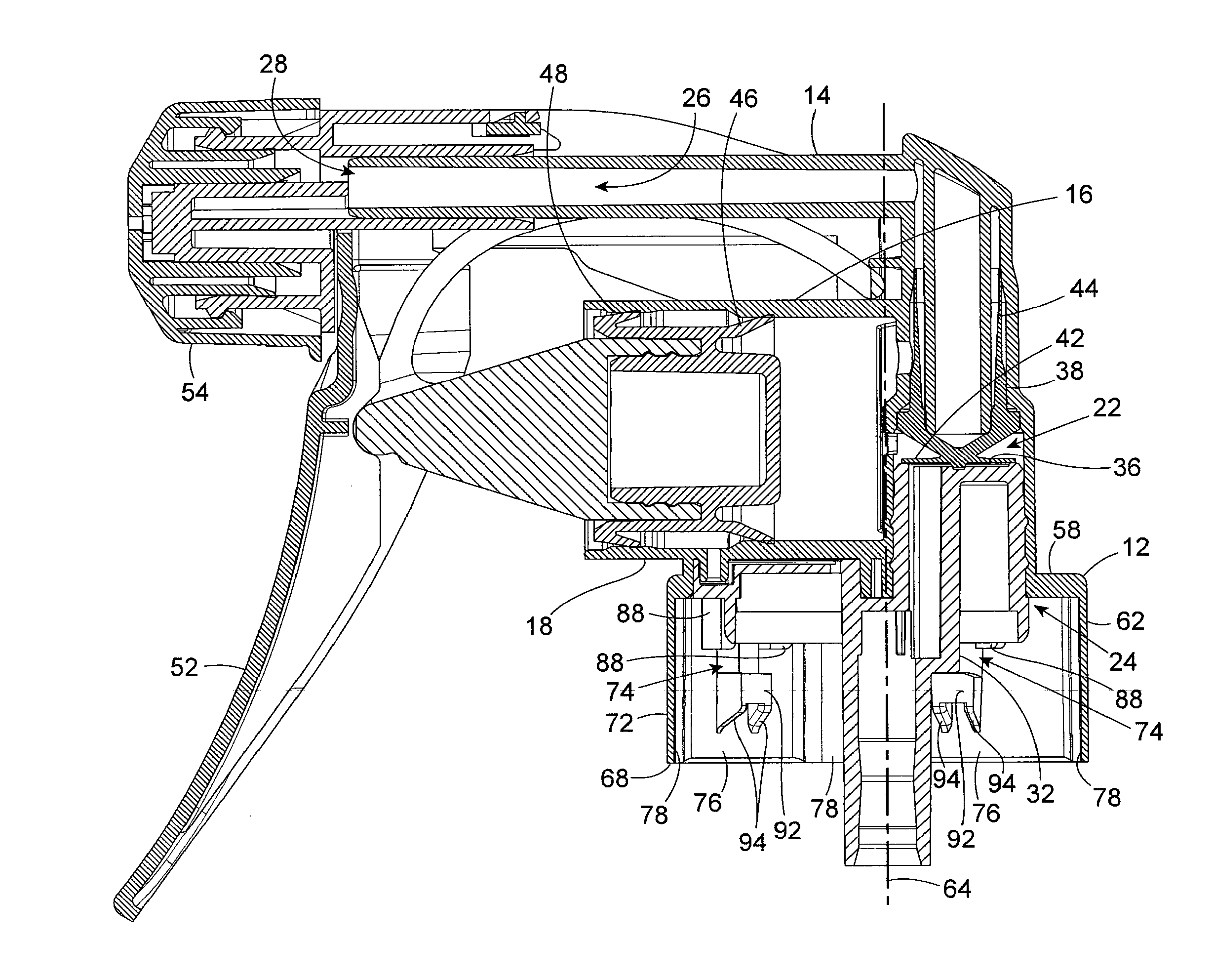
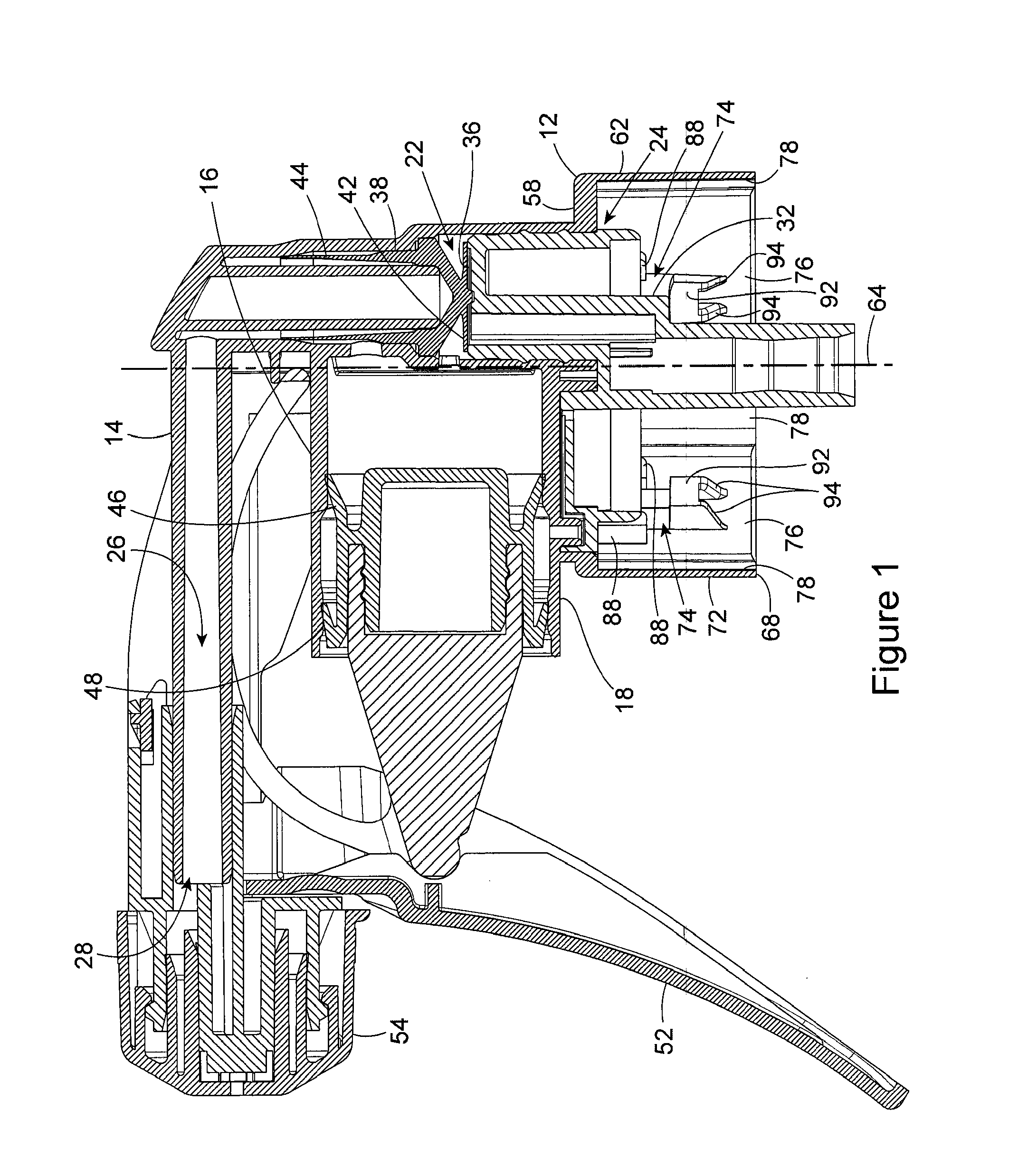
[0035]FIG. 1 shows an example of a trigger sprayer construction employing the connector apparatus of the present invention. It should be understood that the trigger sprayer construction shown in FIG. 1 is only one example of a trigger sprayer that can employ the connector apparatus of the present invention. There are various other different designs of trigger sprayers that are equally well suited for use with the connector apparatus of the invention. Furthermore, the connector apparatus of the invention is shown in FIG. 1 as one, integral piece with the sprayer housing of the trigger sprayer. In the preferred embodiment of the invention, the connector apparatus is connected as a single piece with the sprayer housing. However, in alternate embodiments of the invention, the connector apparatus could be a separate piece from the trigger sprayer housing that is assembled to the trigger sprayer housing. Because the trigger sprayer shown in FIG. 1 is only one example of a trigger sprayer ...


PUM


Abstract

A trigger sprayer has a venting apparatus with a unique construction that is formed by the combination of a sprayer housing of the trigger sprayer and a plug seal assembled to the sprayer housing. The plug seal includes a dip tube connector, a valve seat, an annular rim seal, and a portion of the air vent baffle apparatus that are combined as one integral piece.

Description

[0001] This patent application is a divisional of application Ser. No. 11 / 374,916, which was filed on Mar. 14, 2006, and is currently pending.BACKGROUND OF THE INVENTION [0002] (1) Field of the Invention [0003] The present invention pertains to a trigger sprayer having a unique plug seal that is assembled between the trigger sprayer and an attached liquid container. In particular, the present invention pertains to a trigger sprayer that has a plug seal that includes a dip tube connector, a valve seat, an annular rim seal, and an air vent baffle that are all formed as one integral piece. [0004] (2) Description of the Related Art [0005] Trigger sprayers are those types of sprayers that can be held in a single hand of the user and operated by the fingers of the user's hand to pump liquid from a bottle connected to the trigger sprayer. A trigger sprayer typically comprises a sprayer housing that contains a pump chamber, a liquid supply passage that communicates a liquid inlet opening on...

Claims


Application Information

Patent Timeline
IPC IPC(8): B05B11/00B67D7/58
CPCB05B11/0016B05B11/0029B05B11/3077B05B11/3045B05B11/3074B05B11/3011B05B11/0044B05B11/1045B05B11/1011B05B11/1077B05B11/1074
Inventor FOSTER, DONALD D.NELSON, PHILIP L.CLYNES, WALTER J.
Owner CONTINENTALAFA DISPENSING CO
Why Eureka
Try Eureka