Mixing Pump Device and Fuel Cell

a technology of mixing pump and fuel cell, which is applied in the direction of positive displacement liquid engine, pump, machine/engine, etc., can solve the problems of complicated device design and complicating efforts to reduce size and cost, and achieve the effect of reducing cost, simplifying device design, and being less expensiv

Inactive Publication Date: 2009-05-21
SANKYO SEIKI MFG CO LTD +1
View PDF7 Cites 19 Cited by
  • Summary
  • Abstract
  • Description
  • Claims
  • Application Information

AI Technical Summary

Benefits of technology

[0018]Here, water containing evolved water that evolved in the electromotive portion can be delivered into the pump chamber via the diluent inflow passage. For example, evolved water that evolved in the electromotive portion could be recovered in a water tank and then introduced into the pump chamber from the water tank via the diluent inflow passage. According to such an arrangement, evolved water that evolved in the electromotive portion can be reused efficiently, so discharge of water can be kept to a minimum, or eliminated altogether.
[0019]Next, where a plurality of the outflow passages communicate with the pump chamber, one of the outflow passages can be used as a coolant outflow passage for delivering a coolant to the electromotive portion. According to such an arrangement, cooling of the electromotive portion can be carried out by the mixing pump device embodying the invention, eliminating the need for a dedicated coolant delivery unit.
[0020]Where cooling is carried out in this manner, in preferred practice, only water will be drawn in from the inflow passage, and the coolant outflow passage will deliver cooling ...

Problems solved by technology

This need for a mechanism to detect the operating phase of the pump makes the...

Method used


Image

  • Mixing Pump Device and Fuel Cell
  • Mixing Pump Device and Fuel Cell
  • Mixing Pump Device and Fuel Cell

Examples


Embodiment Construction

[0037]The present invention will be described hereinbelow with reference to the accompanying drawings.

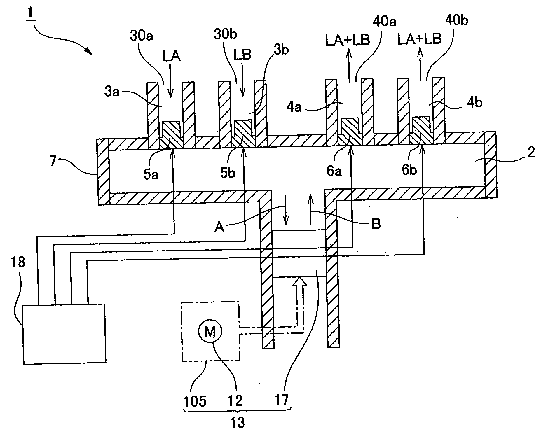
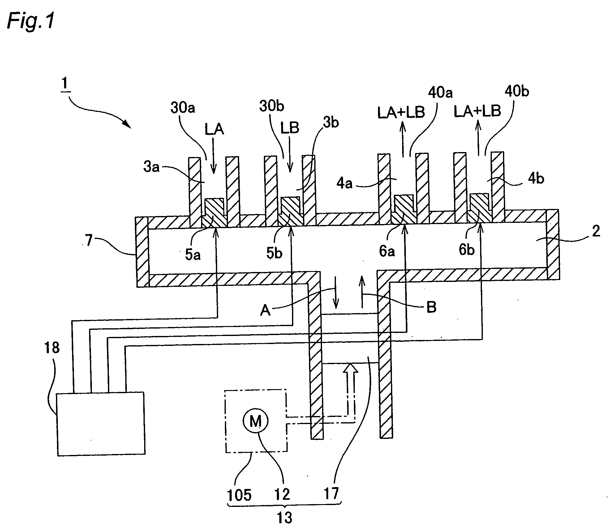
[0038]FIG. 1 is a conceptual diagram showing the basic configuration of a mixing pump device embodying the present invention. As illustrated in FIG. 1, the mixing pump device 1 has a pump chamber 2. In the pump chamber 2 there are formed a plurality (two, in this example) of intake ports 30a, 30b; and a plurality (two, in this example) of discharge ports 40a, 40b. The intake ports 30a, 30b communicate respectively with inflow passages 3a, 3b; and the discharge ports 40a, 40b communicate respectively with outflow passages 4a, 4b. The pump device main unit 7 is made up of the pump chamber 2, the intake ports 30a, 30b, the discharge ports 40a, 40b, the inflow passages 3a, 3b, and the outflow passages 4a, 4b.

[0039]Inflow-side active valves 5a, 5b for individually opening and closing the intake ports 30a, 30b are disposed in these ports. Outflow-side active valves 6a, 6b for individuall...


PUM


Abstract

In a mixing pump device (1), during an suctioning step a stepping motor (12) rotates in a first direction, so that during this time, a plurality of fluids can be drawn in prescribed proportions into a pump chamber (2), by sequentially opening and closing active valves (5a, 5b) situated in inflow passages (3a, 3b) while active valves (6a, 6b) situated in outflow passages (4a, 4b) are in a closed state. During the discharging step the stepping motor (12) rotates in a second direction, so that during this time, a mixed fluid can be discharged from the pump chamber (2) simply by sequentially opening the active valves (6a, 6b) situated in the outflow passages (4a, 4b), while the active valves (5a, 5b) situated in the inflow passages (3a, 3b) are in a closed state. It is possible thereby to achieve a mixing pump device capable of mixing a plurality of fluids in prescribed proportions, without detecting the operating stage of the pump.

Description

TECHNICAL FIELD[0001]The present invention relates to a mixing pump device for suctioning and mixing a plurality of fluids and then discharging them, as well as to a fuel cell for use as a fuel delivery device for delivering fuel to the electromotive part of the mixing pump device.BACKGROUND ART[0002]One mixing pump device known in the art for mixing a plurality of fluids in prescribed proportions is an apparatus designed to suction a plurality of fluids into a single pump chamber, mix them in the pump chamber to form a mixed fluid, then discharge the mixed fluid from the pump chamber. Patent Citation 1 discloses a mixing pump device in a high-performance liquid chromatography device, for suctioning in and mixing several types of solvents with a plunger pump, and discharging the mixed fluid obtained thereby to the column.[0003]The mixing pump device disclosed therein is designed to transmit rotation of a stepping motor to the plunger via a cam mechanism, increasing or decreasing the...

Claims


Application Information

Patent Timeline
IPC IPC(8): H01M8/04F04B43/02F04B49/22F04B49/20
CPCB01F5/0685F04B13/02F04B43/04Y02E60/50H01M8/1011H01M8/1013H01M8/04201B01F25/4512F05B2210/13Y10S417/00
Inventor YOKOZAWA, MITSUOMURAMATSU, KENJIKOZU, KATSUMIICHINOSE, TOSHIHIKO
Owner SANKYO SEIKI MFG CO LTD
Why Eureka
Try Eureka