Coupling structure and use method of combined type trolley case

A technology of connecting structures and trolley cases, applied in applications, luggage, clothing, etc., can solve problems such as low efficiency, high rework rate, easy confusion, etc., to reduce deformation and damage, reduce packaging and transportation costs, and reduce volume Effect

Pending Publication Date: 2019-03-22
芊茂(浙江)拉链有限公司
View PDF1 Cites 21 Cited by
  • Summary
  • Abstract
  • Description
  • Claims
  • Application Information

AI Technical Summary

Problems solved by technology

However, in the production process of the luggage (the chain belt is inserted into the zipper head), it needs to be inserted twice, and it is difficult to assemble the customs lock on the luggage and the pull tab on the slider to make the left and right pull tabs twice. The correct matching of the corresponding direction, customer feedback often causes workers to wear the wrong slider or it is difficult to distinguish the direction of the slider (mainly the two zipper sliders on the same chain belt are set oppositely, in order to make the slider on the slider and the slider The customs lock is set on one side of the zipper, and the installation of the two zippers on the zipper puller should actually be installed in reverse, so the two zipper pullers are not the same, but at first glance, the two zipper pullers are almost the same, it is easy confusion), resulting in high rework rates
When wearing the head, it is necessary to hold the two huge left and right box covers at the same time, which is very laborious and inefficient
In addition, adhesive tape connecting strips are used to connect the upper and lower case shells. When the lid of the trolley case is opened, due to the softness of the adhesive tape connecting strips, the opened and flipped box lid will shake and be unstable, and the T-shaped plate has no similar door. Shaft rotation function, the upper and lower cases cannot be flipped to 180 degrees, and they are in a fully unfolded state, so that the invention can only be used on soft-shell bags, not hard-shell bags, and the occasions of use are subject to certain restrictions , needs further improvement

Method used


Image

  • Coupling structure and use method of combined type trolley case
  • Coupling structure and use method of combined type trolley case
  • Coupling structure and use method of combined type trolley case

Examples


Embodiment 1

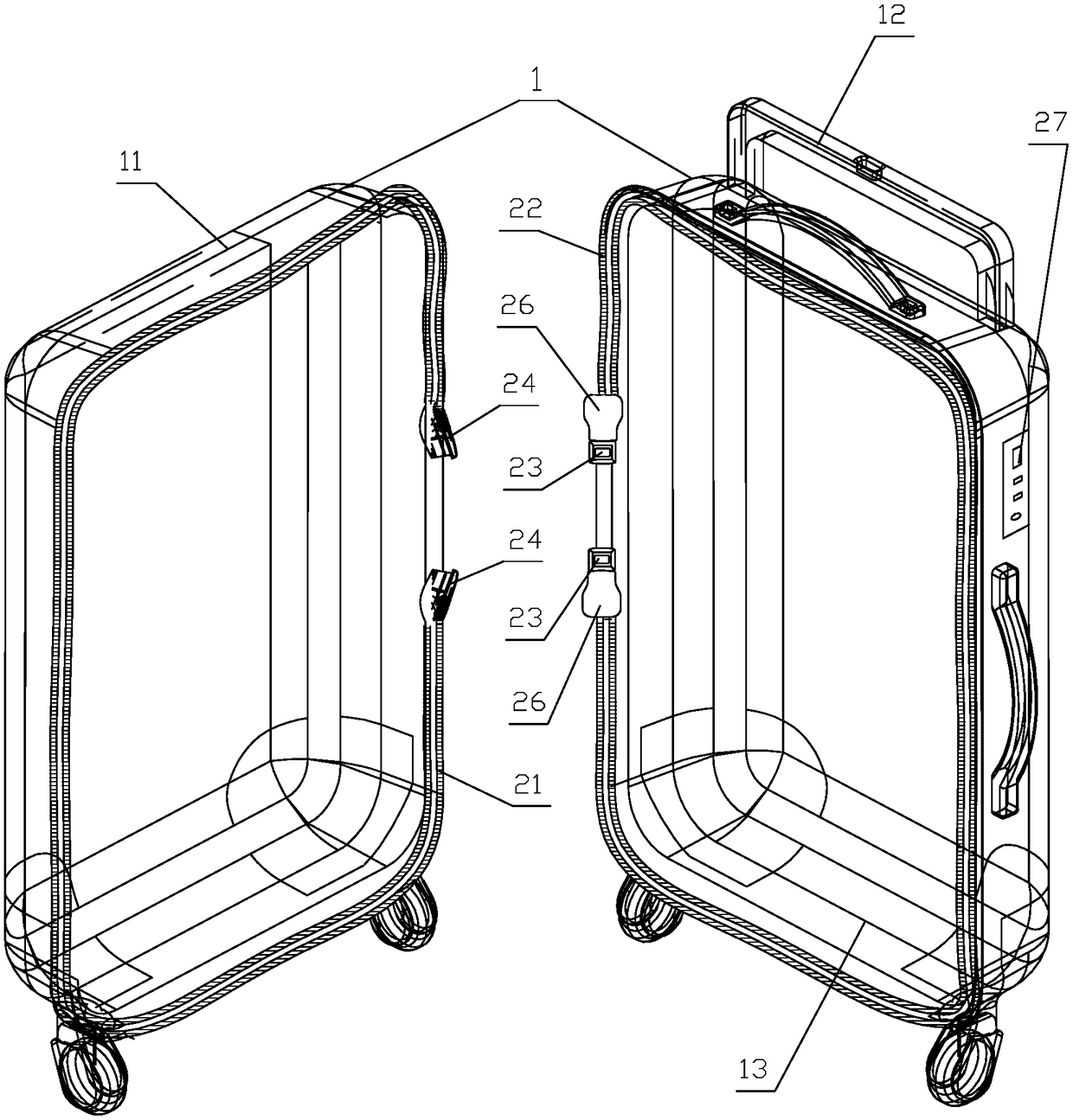
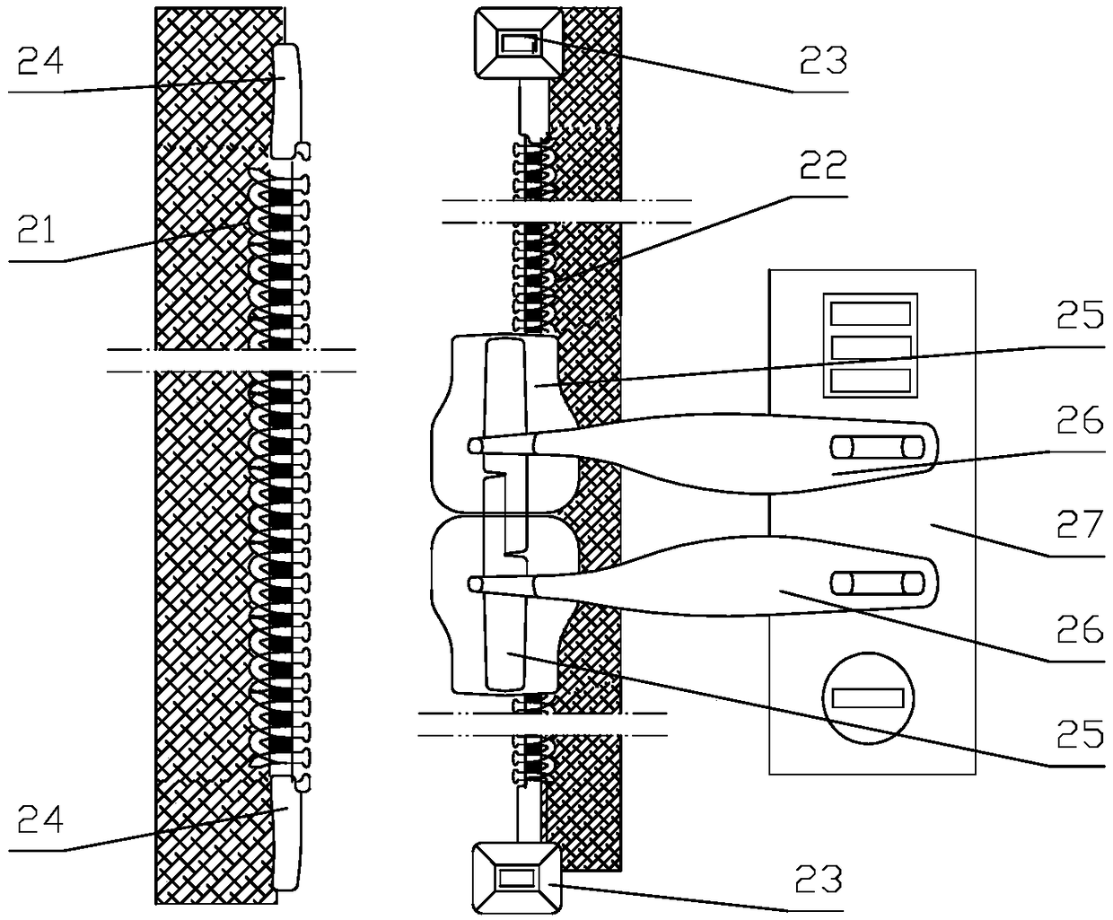
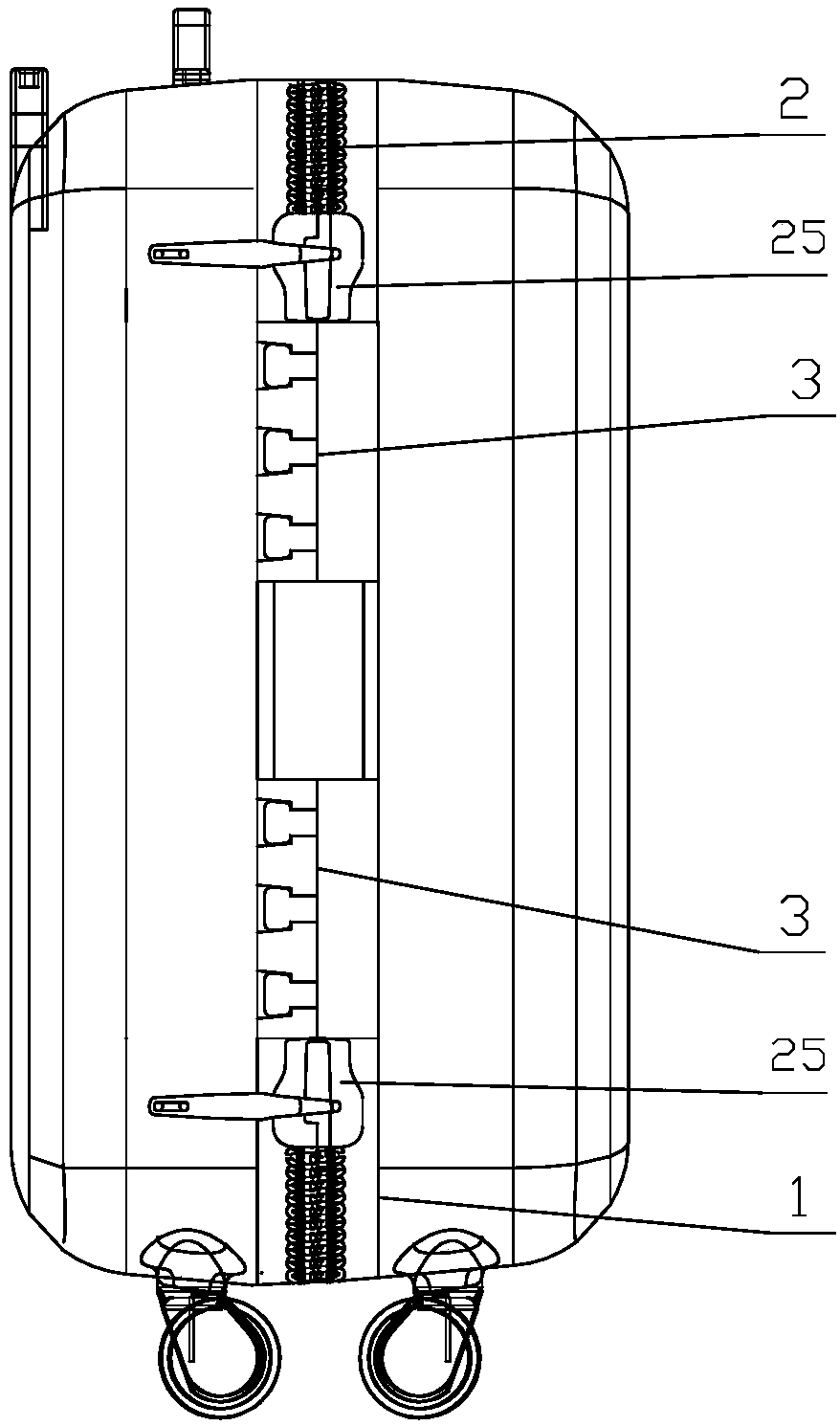
[0044] A connection structure of a combined trolley case, which comprises a soft cloth case or an upper case 11 of a hard case 1 and a lower case 13 equipped with a pull rod 12, the upper case 11, the lower case 13 is sewn around the mouth edge of the zipper 2 at both ends with the single-side chain belt A21 and the single-side chain belt B22 respectively, wherein the single-side chain belt B22 is sewn on the lower box shell 13, as shown in Figure 1 . And the two ends of described unilateral chain belt B22 are all equipped with lower gear 23, and the two ends of unilateral chain belt A21 are all installed with the latch 24 that matches lower gear 23; The slider 25, and the pull tab 26 on the slider 25 can turn to the side of the customs lock 27 and lock with the customs lock 27, as shown in FIG. 2 . Two detachable and mutually fastening soft fastening components 3 are respectively sewn and fixed on the two ends of the upper box shell 11 and the lower box shell 13 connecting p...

Embodiment 2

[0047] For the upper box shell 11 between the two fastening components 3 in embodiment 1, the lower box shell 13 is sewed with a disengagement hinge 4, it is also possible to adopt another coupling structure of a combined drawbar box, and its remaining structures are the same as The above-mentioned Example 1 is the same. And at the two ends of the upper box shell 11, the lower box shell 13 connection parts are respectively fixed with two detachable and snap-fit ​​soft fastening components 3, and between the two fastening components 3, the upper box shell 11, The lower box shell 13 is fixed with a detachable hinge 5 such as Figure 15 , Figure 16 As shown, the upper box shell 11 and the lower box shell 13 are connected together, and the described detachable hinge 5 is as Figure 17 , Figure 18 Shown to comprise two back-to-back flexible L-shaped connecting pieces 51, the top of the two connecting pieces 51 is covered with a П-shaped umbrella cover 52, a supporting plate 53...

Embodiment 3

[0049] Since the upper case 11 and the lower case 13 can be conveniently disassembled structurally, in order to increase the volume of the trolley case 1, an annular thickening can also be connected between the above-mentioned upper case 11 and the lower case 13 by a zipper. Case 6 such as Figure 19 shown. Described thickened case shell 6 is as Figure 20 Shown is an annular ring 61 with the same shape as the mouth of the upper case 11 or the lower case 13, and the two sides of the annular ring 61 are respectively sewn with the unilateral chain belt on the upper case 11 and the lower case 13. A21 and unilateral chain belt B22 matching unilateral chain belt B22 and unilateral chain belt A21, and use two sliders 25 to open and close the zipper 2 at both ends of the thickened box shell 6 sides and the upper box shell 11 and the lower box shell 13 connections. Of course, the thickness (or width) S of the thickened box shell 6 can be designed to have a variety of thickness S va...


PUM


Abstract

The invention discloses a coupling structure and a using method of a combined type trolley case. The combined type trolley case comprises an upper casing with a soft cloth box shell or a hard shell trolley box, and a lower casing with a pull rod, wherein a unilateral zipper belt A and a unilateral zipper belt B of a two open ends zipper, which are opened or closed to each other, are sewed at the periphery of the edges of the upper casing and the lower casing; lower gears are mounted at two ends of the unilateral zipper belt B; bolts matched with the lower gears are mounted at the two ends of the unilateral zipper belt A; two opposite pull heads are mounted on the unilateral zipper belt B; a zipper pull on each pull head can be turned to one side of a customs lock to be locked with the customs lock; two soft fastening components that are fastened to each other are respectively fixed on the two ends of a joint part of the upper casing and the lower casing; detachable hinges are fixed onthe upper casing and the lower casing between the two fastening components, so as to connect the upper casing and the lower casing together, and shield gaps at the two ends of the two open ends zipper. The rework caused by a mistake after the sewing and threading of the unilateral zipper belt can be avoided.

Description

technical field [0001] The invention relates to a structure and a use method of a trolley case, and further includes a connection structure and a use method of a combined trolley case. Background technique [0002] There is a patent ZL201610081999.6 Name: Two-way corresponding positioning and opening zipper luggage sewing processing method and double-end opening zipper luggage structure, the zippers on the left and right lids are: the left and right chain belts are equipped with a bottom at one end The other end is a latch, and the two opposite zipper pulls are worn on the left and right chain belts respectively. However, in the production process of the luggage (the chain belt is inserted into the zipper head), it needs to be inserted twice, and it is difficult to assemble the customs lock on the luggage and the pull tab on the slider to make the left and right pull tabs twice. The correct matching of the corresponding direction, customer feedback often causes workers to w...

Claims


Application Information

Patent Timeline
Patent Type & Authority Applications(China)
IPC IPC(8): A45C5/04A45C13/00A45C13/10
CPCA45C5/045A45C13/001A45C13/10A45C13/103
Inventor 王联洲
Owner 芊茂(浙江)拉链有限公司
Why Eureka
Try Eureka