
Attitude insensitive flow device system and method

a flow device and attitude-sensitive technology, applied in the field of flow control, can solve the problems of reducing the effect, reducing the effect, and reducing the zero of the mass flow controller

Active Publication Date: 2006-01-12
BROOKS INSTRUMENT
View PDF9 Cites 19 Cited by
  • Summary
  • Abstract
  • Description
  • Claims
  • Application Information

AI Technical Summary

Benefits of technology

[0008] Embodiments of the present invention provide an attitude insensitive flow device system and method that eliminates, or at least substantially reduces, the shortcomings of prior art flow device systems and methods.
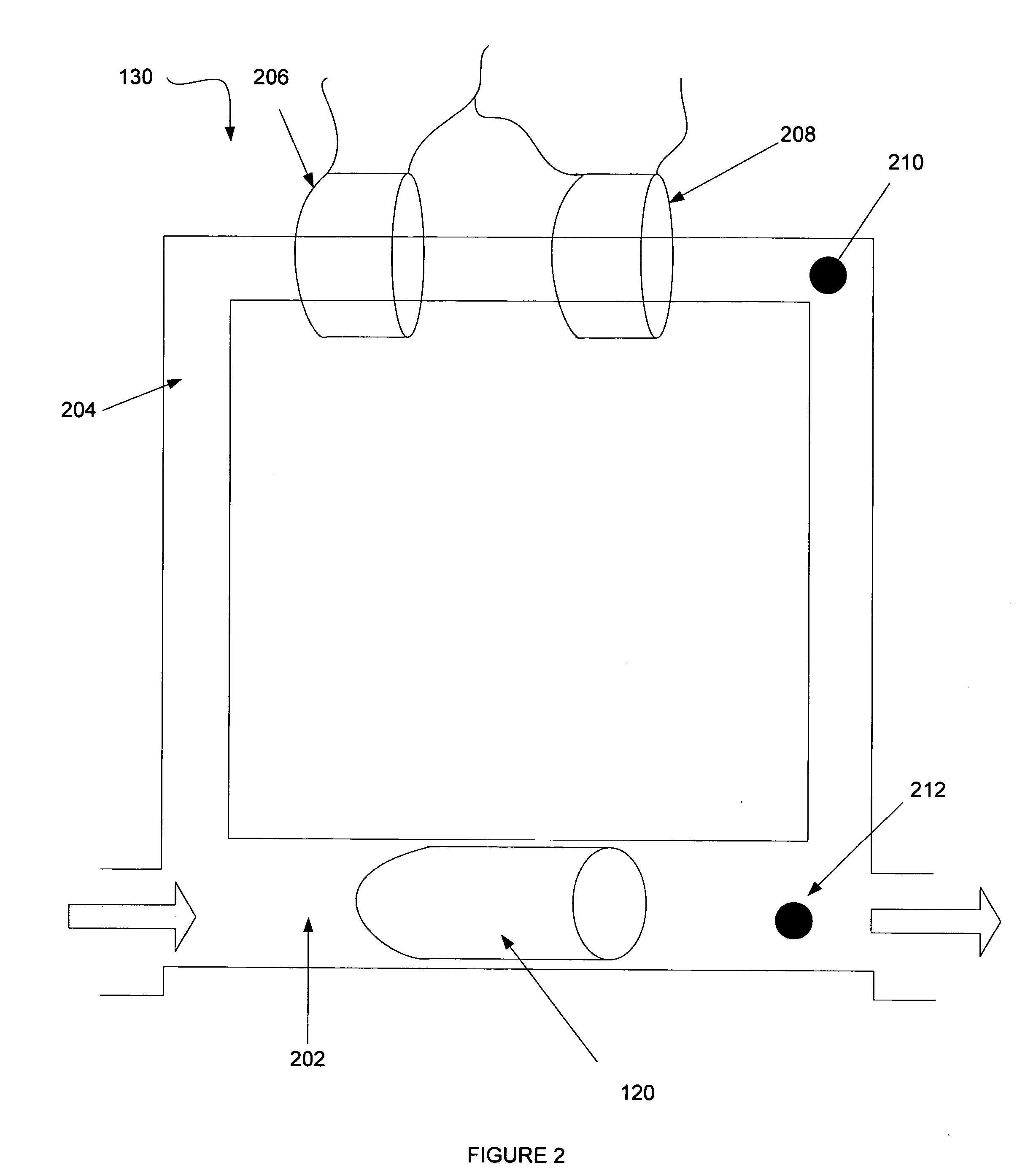
[0013] Embodiments of the present invention provide a technical advantage over prior art mass flow controllers by compensating for thermal siphoning with no or minimal increase to the internal volume of the flow device. Because the internal volume of the flow device is not increased, flow devices according to the present invention can be used in low vapor pressure delivery systems.
[0014] Embodiments of the present invention provide another advantage by allowing the same mass flow controller to be installed in a variety of orientations.
[0015] Embodiments of the present invention provide yet another advantage as the device orientation can be a software accessible parameter that can be used in diagnostics.

Problems solved by technology

While this flow may be small, it can cause measurable changes in the zero of the mass flow controller.
This problem is exacerbated if the attitude (i.e., angle from the horizontal of the main flow path) changes.
While this method reduces the effects of thermal siphoning, a small amount of thermal siphoning remains.
This method can adversely affect sensing in some applications because it increases the differential pressure required across the sensing element.
This method requires a complicated flow path that is difficult to manufacture.
Moreover, this method simply reorients the axis of the capillary tube ninety degrees and will experience the same difficulties as other flow measurement devices if installed in an orientation that is rotated ninety degrees around the main axis of flow relative to the intended installation orientation.
While this system acts to reduce the effects of thermal siphoning, mass flow measurement / control devices incorporating this system can be more expensive to manufacture.
The increase in internal volume can make the device unsuitable for use in systems with low vapor pressure.

Method used


Image

  • Attitude insensitive flow device system and method
  • Attitude insensitive flow device system and method
  • Attitude insensitive flow device system and method

Examples


Embodiment Construction

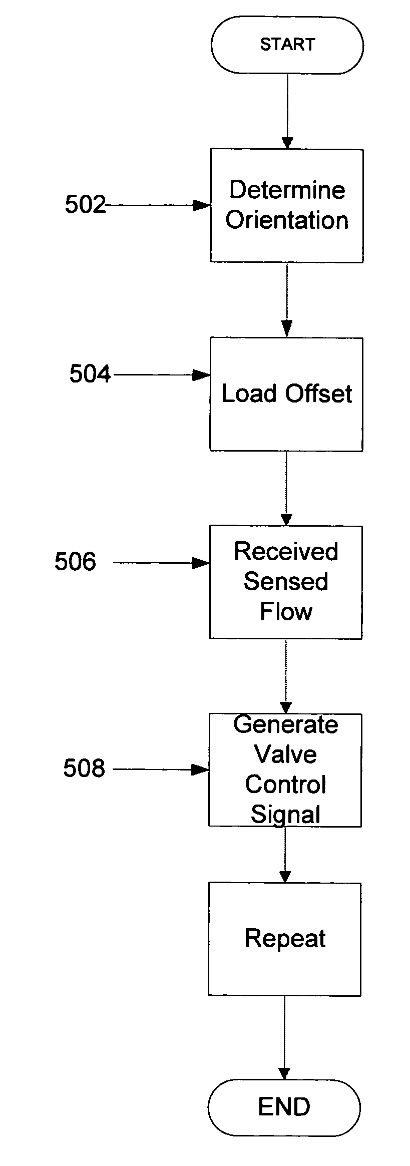
[0022] Embodiments of the present invention provide a system and method for attitude insensitive flow controllers. Embodiments of the present invention can include a flow device with a controller for determining flow. The controller can include an orientation sensor that is sensitive to the angle of the flow device. Based on the reading of the orientation sensor, the controller can apply a predetermined offset to flow measurements to account for thermal siphoning.

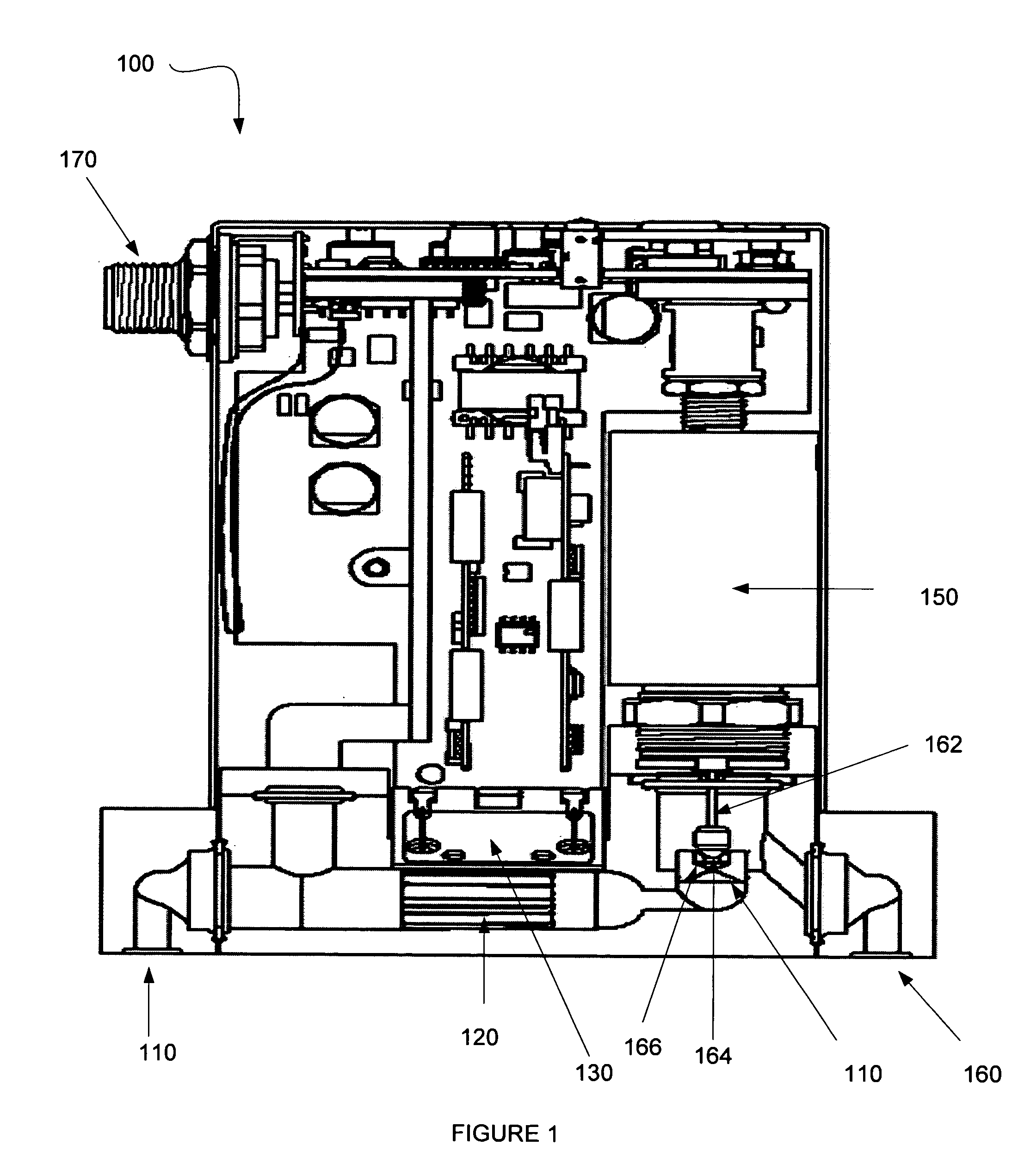
[0023]FIG. 1 is a diagrammatic representation of one embodiment of a flow controller. Mass flow controller 100 comprises inlet fitting 110, flow restrictor 120, thermal mass flow sensor 130, control valve 140, solenoid 150, outlet fitting 160, and I / O coupling 170 for communicating with a control system or process management system. Thermal mass flow sensor 130, which can include upstream and downstream resistors, and solenoid 150 may be coupled to an embedded control system. The control valve is driven by a current contro...


PUM


Abstract

Embodiments of the present invention provide systems and methods for attitude insensitive flow devices. One embodiment of the present invention can include a flow device comprising a processor and a computer readable medium accessible by the processor that stores a set of computer instructions executable by the processor. The computer instructions can comprise instructions executable to receive an orientation, receive a sensed flow, and determine a flow through the flow device based on the sense flow and the orientation.

Description

TECHNICAL FIELD OF THE INVENTION [0001] Embodiments of the present invention relate to the field of flow control. More particularly, embodiments of the present invention relate to systems and methods for an attitude insensitive flow device. BACKGROUND OF THE INVENTION [0002] The manufacture of semiconductors typically requires precise control of fluids (e.g., gasses, liquids, gas-vapor mixes) through the process path to a process chamber. Regulation of mass flow is often achieved through the use of a thermal mass flow controller. These mass flow controllers generally operate by directing fluid flow through a capillary tube path that runs parallel to a bypass area of the main flow path. Two thermally sensitive resistors are wound around the capillary tube. As fluid travels through the capillary tube, heat is conducted away from the resistors, or imparted to the fluid, causing the resistance of each of the resistors to change and the temperature of the fluid to change. Based on the di...

Claims


Application Information

Patent Timeline
Patent Type & Authority Applications(United States)
IPC IPC(8): G01F1/684G01F1/00
CPCG01F1/688G05D7/0635G01F5/00G01F1/6965Y10T137/7759Y10T137/776G01F1/00G01F7/00
Inventor LARSON, DWIGHT S.
Owner BROOKS INSTRUMENT
Learn More