[0016] The applicants have found that the introduction of a
system of transfer gears into a control unit can provide a control unit which is both compact and easy to operate. The transfer gears provide a
mechanical advantage, facilitating easy operation of the blind by the user. The use of a gear reduction by
transfer system comprising a inner ring gear, an outer ring gear and one or more intermediate gears wherein the intermediate gears may rotate upon their own axes but not around the
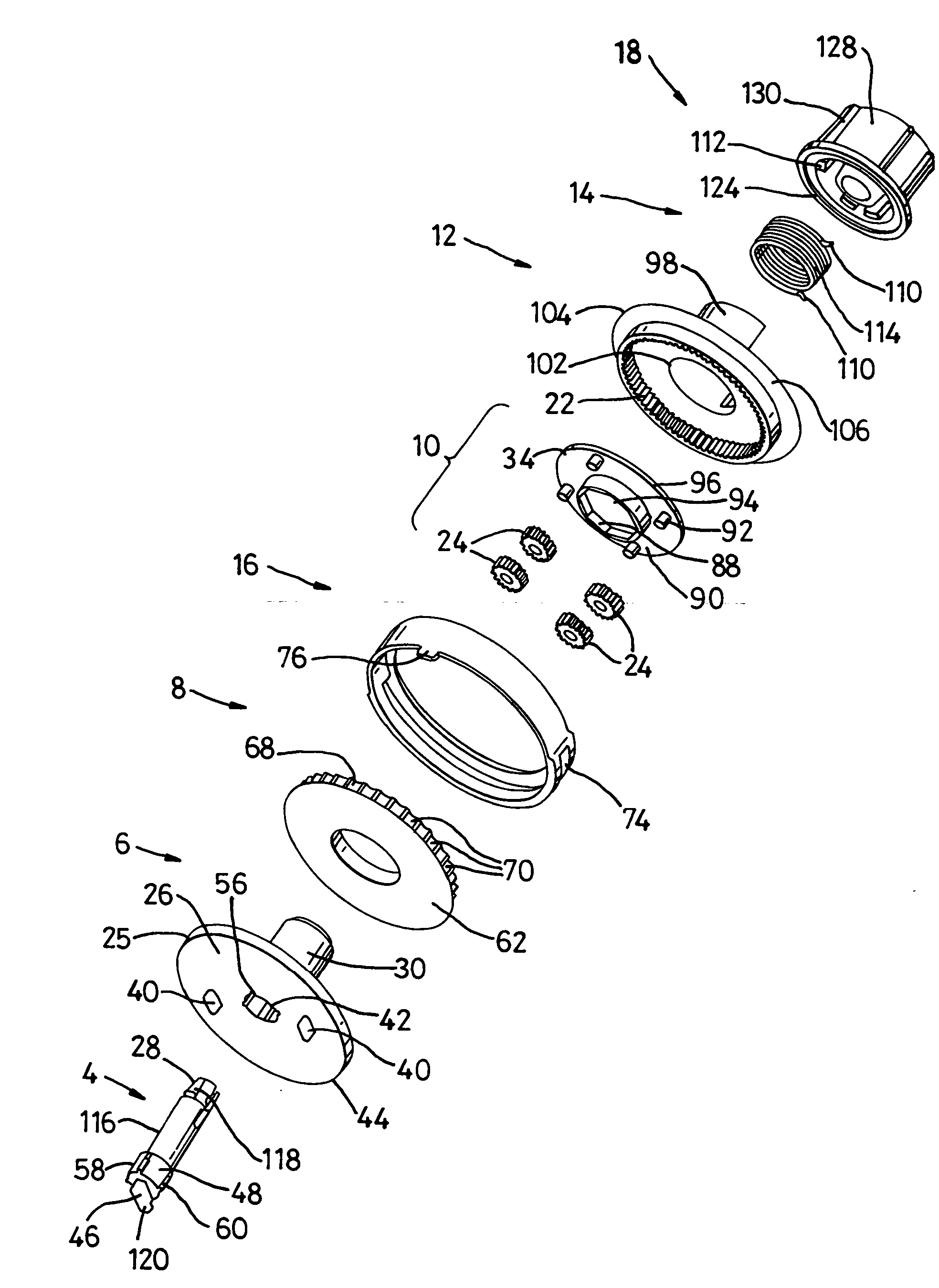
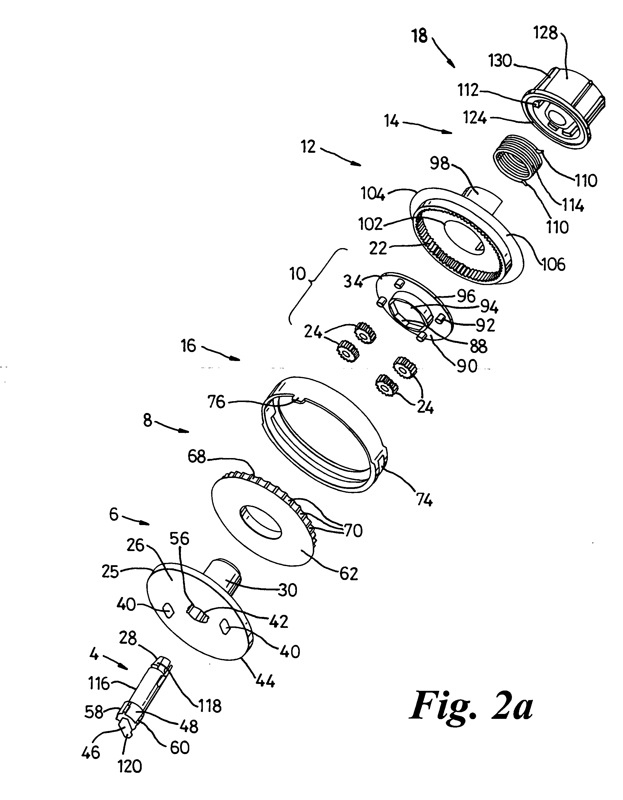
rotational axis of the inner ring gear, and wherein each intermediate gear is meshed with both the inner and outer ring gears, offers substantial gear reduction ratios in a compact unit. Further, the transmission of rotational motion in the invention is via the outer ring gear, which in turn is part of the driven member. This component may be more robust than the planetary gear mounting plates of the prior art, thereby prolonging the life of the control unit.
[0023] The intermediate gear or gears are preferably mounted on a non-rotatable plate. The plate may comprise a substantially planar annular disc mounted on an axially central substantially cylindrical portion. The face of the non-rotatable plate on which the intermediate gears are not mounted may comprise a cylindrical portion extending outward from the inner edge of the annular plate. In one embodiment the cylindrical portion provides a friction surface for interaction with the braking means. This interaction controls the speed of rotation of the elements of the control unit providing a braking effect in the absence of rotation. Where the cylindrical portion of the non-rotatable plate functions as a friction surface, the cylindrical portion of the
sprocket support is preferably absent.
[0025] It is to be appreciated that other numbers of intermediate gears may be used, such as from one to six intermediate gears. In preferred embodiments between three and five intermediate gears are used. If the intermediate gears are to be equidistantly spaced around the inner ring gear, it is preferable that an odd number of gears are used. This limits movement of the inner ring gear within the
transfer system to one direction relative to the outer ring gear at any time. This prevents unequal wear and eccentric movement of the inner ring gear. Eccentric movement of the inner ring gear is undesirable as this may make the
system more difficult to operate. It is therefore preferable that there are three or five intermediate gears, most preferably three.
[0033] Where more than one wrap spring is used, the internal volume of the control unit may be increased. One aim of the invention is to produce a compact control unit; as a result, the addition of further wrap springs is undesirable. Where wrap springs are used in the invention, they may be of circular or rectangular cross-section. Preferably, they will be of generally circular cross-section, with modified wrap spring juts. Where the juts have been modified, the modification will be such that each jut has one or more flattened surfaces, and if only one surface has been flattened that this is on the face of the jut which contacts the edges of the cutaway portion of the driven member. If the cross-sectional shape of the juts is modified in this way, the contact area of the spring with the driven member contact surface is increased, improving purchase and decreasing wear of the driven member in use.
[0035] The control unit also includes a sprocket support. In one embodiment, the sprocket support comprises a roughly cylindrical portion and connected to one end, a collar which forms the external face of the sprocket support, and which is substantially annular. The cylindrical portion of this component extends directly from the inner edge of the sprocket support face engaging the driven member and provides a friction surface for interaction with the braking means. Where the friction surface forms part of the sprocket support, the interaction of the friction surface with the braking means controls the speed of rotation of the elements of the control unit in use, and also provides a braking effect in the absence of rotation. In an alternative embodiment, the friction surface is the cylindrical portion of the non-rotatable plate. In this embodiment the cylindrical portion of the sprocket support is preferably substantially absent.
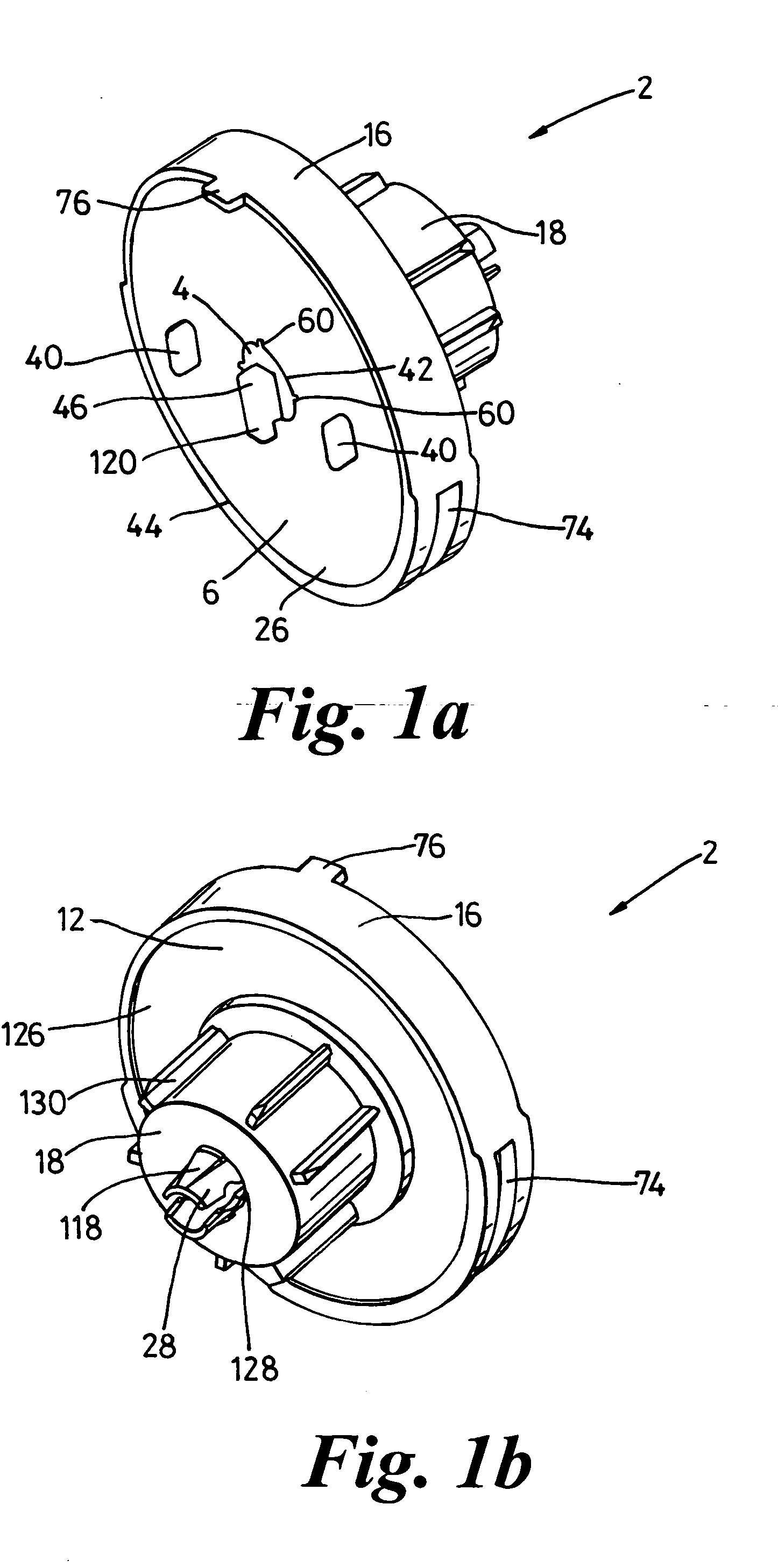
[0041] Optionally, the control unit may also include a chain guard housing. Where present, the chain guard housing of the invention covers the driving
pulley and is preferably substantially flush with the external face of the sprocket support collar when the unit is assembled, however this is not essential. Covering the driving pulley in this way prevents the chain from becoming dislodged during use, and provides a more aesthetically pleasing unit to the user.

