Methods and apparatus for expressing body fluid from an incision

a body fluid and incision technology, applied in the field of lancing devices, can solve the problems of difficult blood transfer directly to test devices, less likely to provide excellent blood samples, and significant pain in many patients

Inactive Publication Date: 2010-11-30
ROCHE DIABETES CARE INC
View PDF362 Cites 41 Cited by
  • Summary
  • Abstract
  • Description
  • Claims
  • Application Information

AI Technical Summary

Benefits of technology

[0023]Therefore, it is another object of the invention to provide a lancet carrier which eliminates the above-mentioned shortcomings.

Problems solved by technology

However, the nerve density in this region causes significant pain in many patients.
These sites are also less likely to provide excellent blood samples and make blood transfer directly to test devices difficult.
Repeated lancing in limited surface areas (such as fingertips) results in callous formation.
This leads to increased difficulty in drawing blood and increased pain.
In such situations, bringing the finger of a patient directly to the test device poses some risk of contamination from blood of a previous patient.
However, the incision may tend to close around the lancet, thereby limiting the amount of body fluid that can be obtained.
The amount of fluid which can be obtained by way of such non-invasive vibration is minimal, however.
Even with the many improvements which have been made, the pain associated with lancing remains a significant issue for many patients.
The need for blood sampling and the fear of the associated pain is also a major obstacle for the millions of diagnosed diabetics, who do not adequately monitor their blood glucose due to the pain involved.
Because the user knows the precise instant when the lancet will be triggered and pain will be felt, there is a tendency for the user to jerk or raise the device at the instant of triggering, which can lead to inconsistent skin penetration, or possibly no penetration.

Method used


Image

  • Methods and apparatus for expressing body fluid from an incision
  • Methods and apparatus for expressing body fluid from an incision
  • Methods and apparatus for expressing body fluid from an incision

Examples


Embodiment Construction

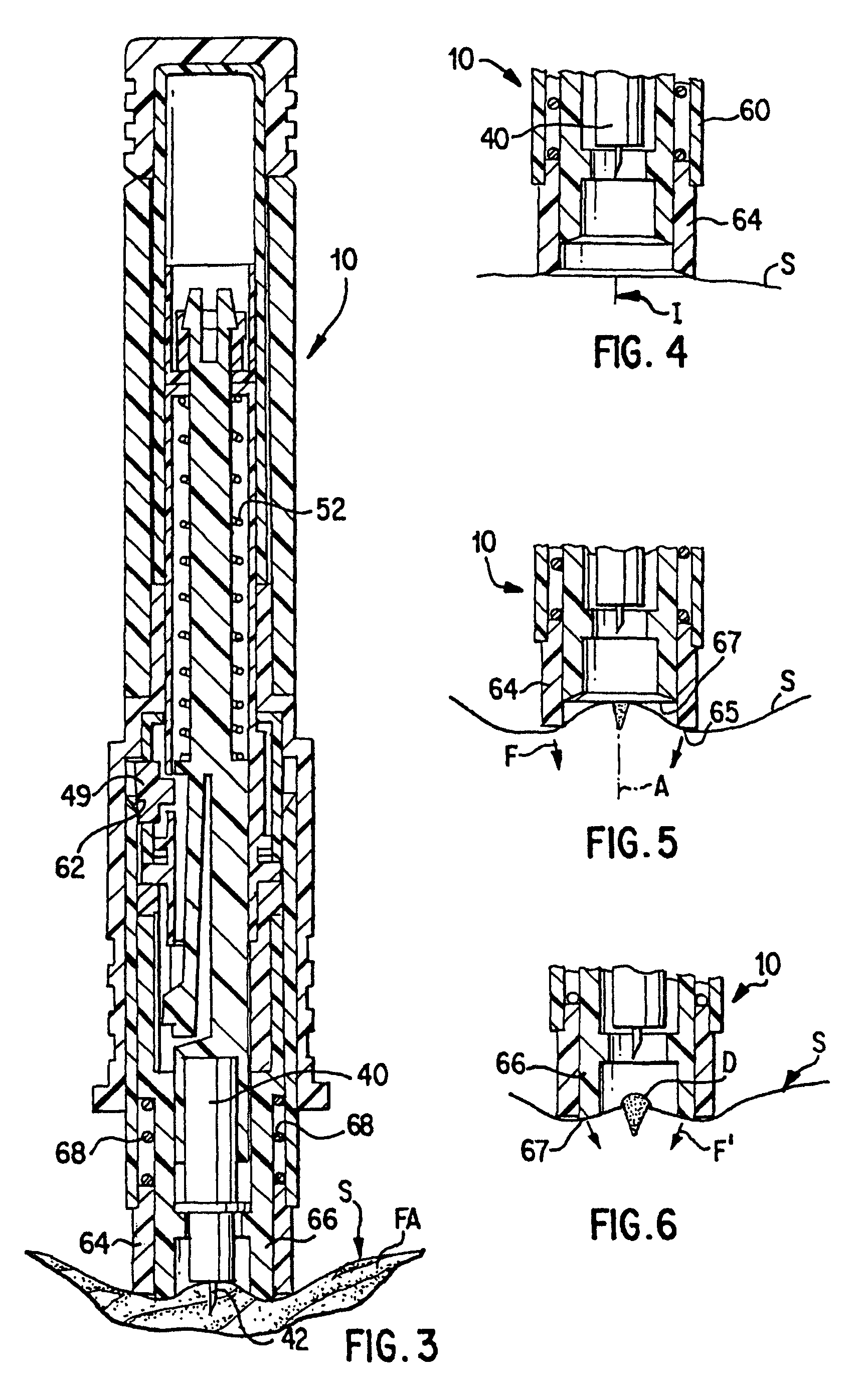
[0054]A lancing device 10 (see FIG. 1) according to one preferred embodiment of the invention comprises an outer housing 12 having upper and lower portions 14, 16 connected together, and an inner housing 18 fixed to the outer housing.

[0055]Mounted for vertical reciprocation in the upper portion 14 of the outer housing 12 is a cocking mechanism 20 comprising a pull handle 22 to which is fixedly secured a hollow draw tube 24. Fixed to an inner wall of the draw tube 24 is a draw ring 26.

[0056]Situated within the draw tube 24 is a draw bar 30 having a pair of flexible hooks 32 at its upper end. The hooks are releasably latched to a sleeve 34 which is movably disposed within the draw ring 26. A coil compression spring 36 acts between a flange 33 of the sleeve 34 and an inner flange 38 of the draw ring 26.

[0057]A trigger sleeve 35 is mounted within the lower portion 16 of the outer housing 12. A lower end of the trigger sleeve rests upon a first outer flange 37A of the inner housing, and ...


PUM


Abstract

A sample of a body fluid such as blood or interstitial fluid is obtained from a body by lancing a portion of a user's skin, preferably in an area other than a finger tip, to form an incision. After the needle has been removed from the incision, a force is applied to depress the skin in a manner forming a ring of depressed body tissue in surrounding relationship to the incision, causing the incision to bulge and the sides of the incision to open, whereby body fluid is forced out through the opening of the incision. A stimulator member is mounted to an end of a lancet-carrying housing for applying the force. The stimulator member can be movable relative to the housing, and can be either heated or vibrated to promote movement of the body fluid.

Description

REFERENCE TO RELATED APPLICATIONS[0001]This application is a continuation of U.S. patent application Ser. No. 09 / 960,806 filed on Sep. 21, 2001, which is a continuation of U.S. patent application Ser. No. 09 / 586,969 filed on Jun. 5, 2000, now U.S. Pat. No. 6,319,210, which is a continuation of U.S. patent application Ser. No. 09 / 238,140 filed on Jan. 28, 1999, now U.S. Pat. No. 6,071,250, which is a continuation of Ser. No. 08 / 858,043 filed on May 16, 1997, now U.S. Pat. No. 5,951,493, which claims the benefit of priority of Provisional Patent Application Ser. Nos. 60 / 017,133 filed May 17, 1996; 60 / 019,918 filed Jun. 14, 1996; 60 / 023,658 filed Aug. 1, 1996; 60 / 025,340 filed Sep. 3, 1996; and to U.S. Patent Application Ser. Nos. 60 / 092,121 filed Sep. 16, 1996; 60 / 064,856 filed Sep. 17, 1996; and 60 / 044,406 filed Oct. 8, 1996; the disclosures of which are incorporated herein by reference.[0002]The present invention is related to inventions disclosed in commonly assigned U.S. patent ap...

Claims


Application Information

Patent Timeline
Patent Type & Authority Patents(United States)
IPC IPC(8): A61B5/00A61B5/15A61B10/00A61B17/00
CPCA61B5/1411A61B5/14532A61B10/0045A61B2010/008A61B2017/00765A61B2562/0295A61B5/150022A61B5/150068A61B5/150076A61B5/150083A61B5/150412A61B5/15111A61B5/15113A61B5/15117A61B5/1519A61B5/15194A61B5/150503
Inventor DOUGLAS, JOEL S.ROE, JEFFREY N.GRAGE, HENRY M.
Owner ROCHE DIABETES CARE INC
Why Eureka
Try Eureka