Collecting lens

a collection lens and lens body technology, applied in the field of two-element collection lens, can solve the problems of blurred image, less “brightness, and difficult to see the effect of improving quality

Active Publication Date: 2010-11-30
TEXAS INSTR INC
View PDF10 Cites 8 Cited by
  • Summary
  • Abstract
  • Description
  • Claims
  • Application Information

AI Technical Summary

Problems solved by technology

This technology is fairly well-developed, but has reached the point where perceptible increases in quality are difficult to achieve.
A CRT also takes up a relatively-large amount of space because the components used for generating the electron stream must be placed at a certain distance from the display screen.
The main challenge is to image the LED source by reducing the light source emission angle onto the DMD without degrading that same etendue (if too much aberration is present making the image blurred and less “bright” than the source).
Due to the alignment issues, the lens system can be extremely difficult and expensive to produce.

Method used


Image

  • Collecting lens
  • Collecting lens
  • Collecting lens

Examples


Embodiment Construction

[0019]The making and using of the embodiments are discussed in detail below. It should be appreciated, however, that the present invention provides many applicable inventive concepts that can be embodied in a wide variety of specific contexts. The specific embodiments discussed are merely illustrative of specific ways to make and use the invention, and do not limit the scope of the invention.

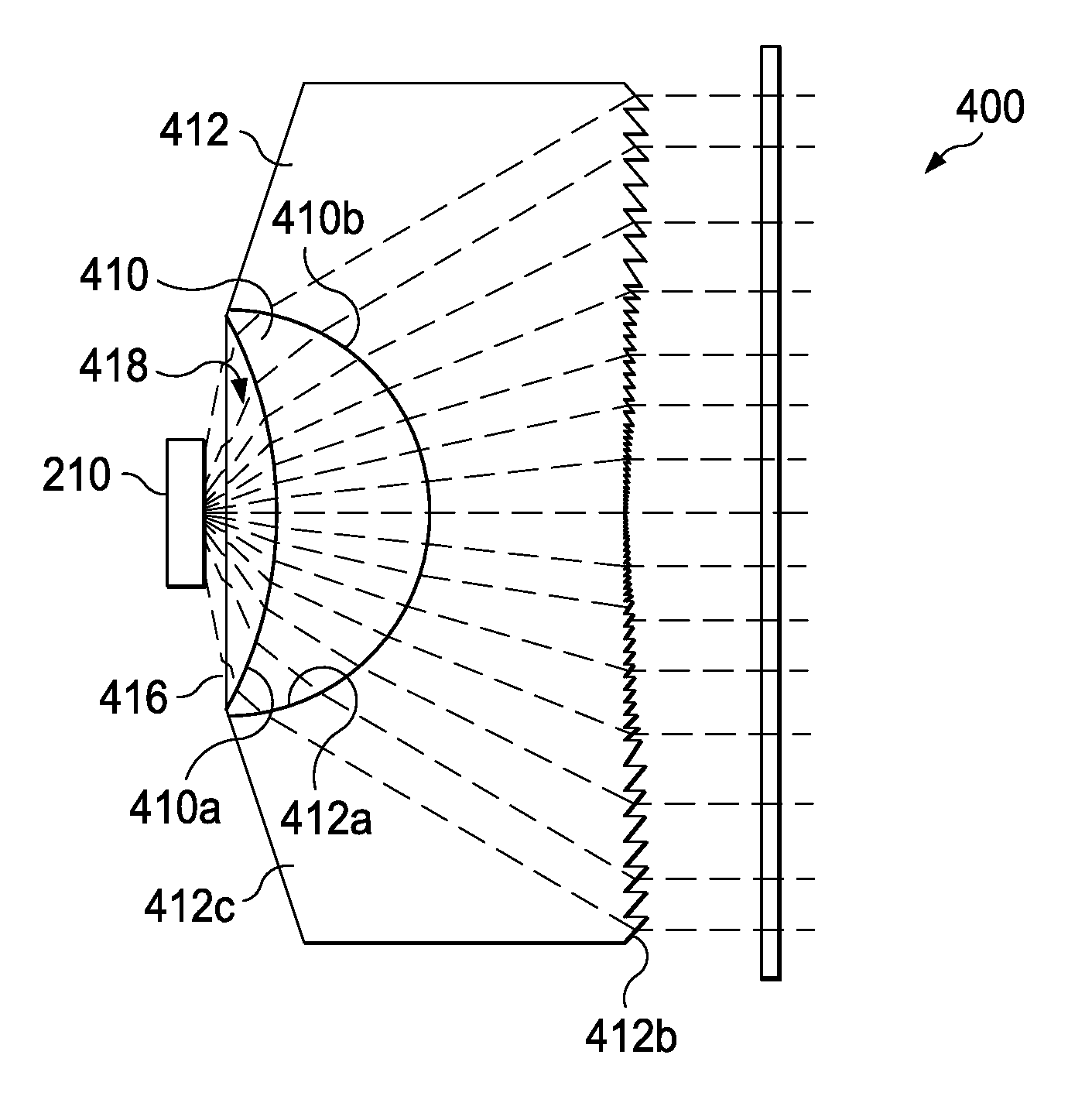
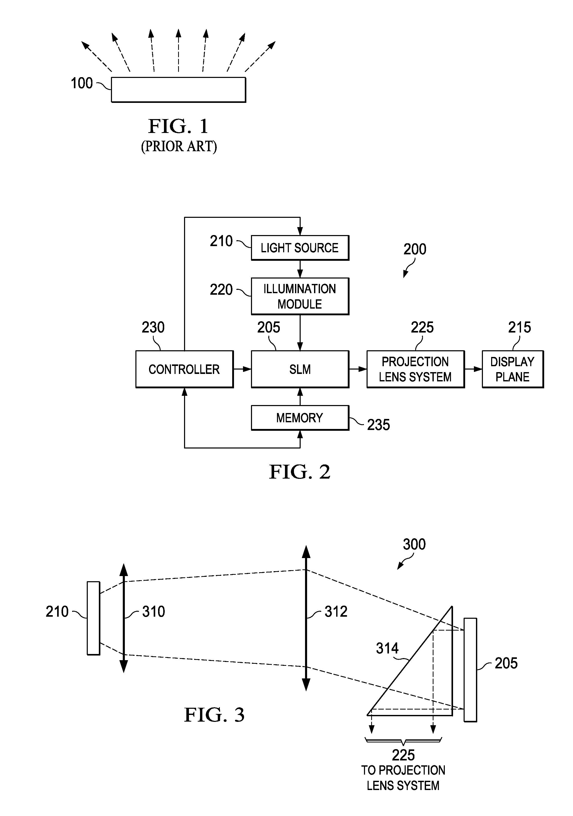
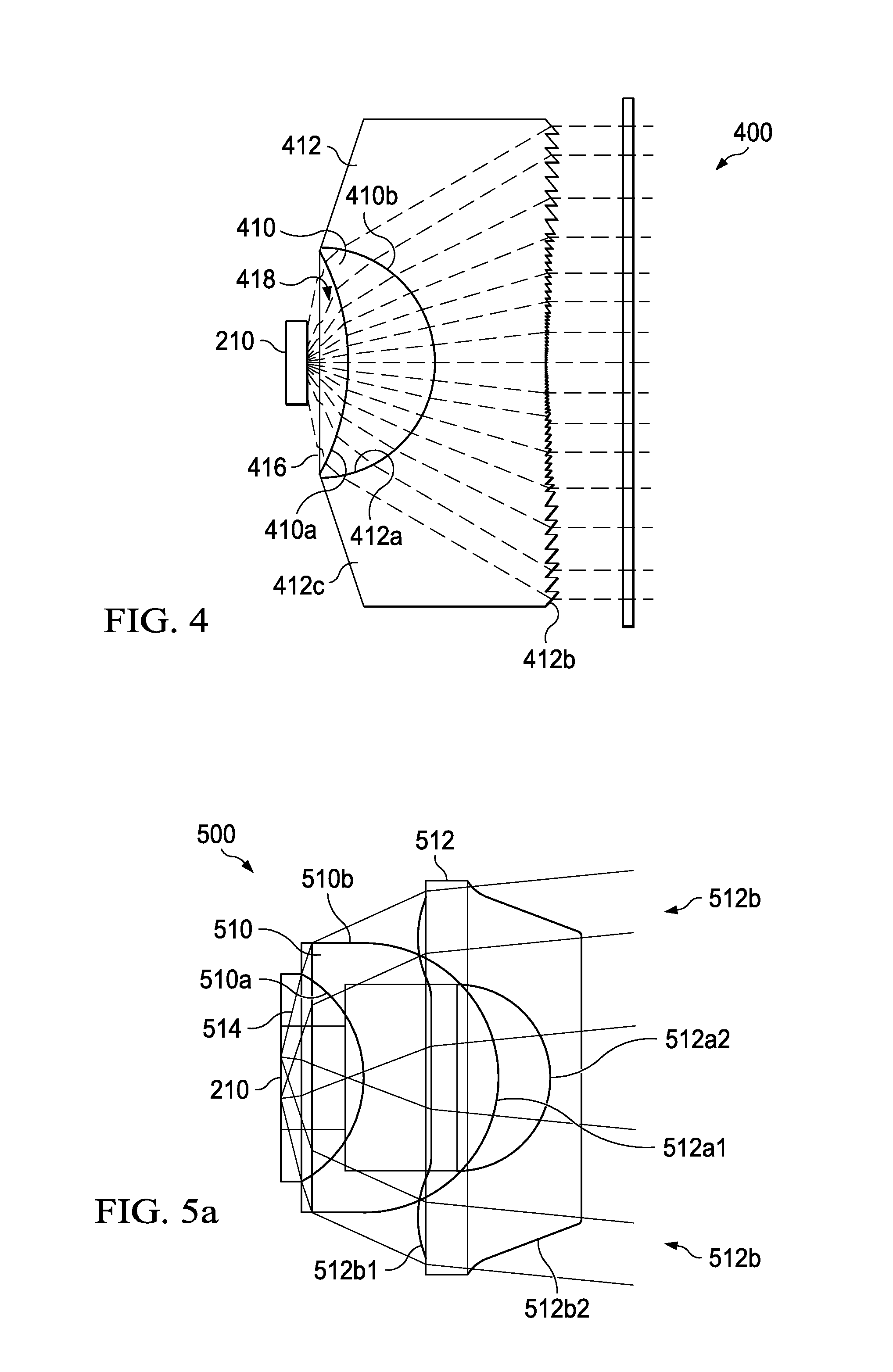
[0020]Embodiments will be described in a specific context, namely, a spatial light modulator (SLM) based projection display system. Embodiments may also be applied, however, to projection display systems, in general, and specifically to other microdisplay-based projection display systems, such as those utilizing transmissive or reflective liquid crystal displays, liquid crystal on silicon, ferroelectric liquid-crystal-on-silicon, deformable micromirrors, and so forth. It should also be appreciated that embodiments described herein are illustrated with reference to specific sizes and materials. O...


PUM


Abstract

A system and method for collimating light emitted from a light source, such as a light-emitting diode (LED), is provided. The system and method includes two lenses, both lenses having a positive power for converging the light rays. In one example, the first lens is a hemispherical ball lens and the second lens is configured such that one surface conforms to the exiting surface of the first lens. The exiting surface of the second lens may be, for example, a Fresnel lens or an aspherical lens. In another example, the first lens may be a hemispherical or a hyperhemispherical ball lens. The second lens has an outer circumference having two aspherical surfaces. The inner portion of the second lens is in direct contact with the first lens. This configuration creates a dual-channel collimator.

Description

TECHNICAL FIELD[0001]Embodiments relate generally to the field of projection display systems and methods, and more particularly, to a two element collecting lens.BACKGROUND[0002]Projection displays are used for a wide variety of applications, such as producing the pictures viewed on television screens. A typical projection display system includes a number of components, including a display screen, a light source, and an optical path between them. To create the pictures, one or more light sources are provided to emit light when it is needed. The light they produce is then manipulated by a series of optical devices in order to create the visual image. The visual image created along the optical path is then displayed on the display screen, the television screen for example, or another visual display. In most cases, the goal is to produce the best picture possible. The key to producing a desirable visual display, of course, is the configuration of the various optical devices along the o...

Claims


Application Information

Patent Timeline
Patent Type & Authority Patents(United States)
IPC IPC(8): G02B9/06G02B9/04F21V5/04
CPCG02B3/10
Inventor DESTAIN, PATRICK RENE
Owner TEXAS INSTR INC
Why Eureka
Try Eureka