Method for manufacturing a camshaft

a manufacturing method and camshaft technology, applied in the direction of metal-working holders, supporters, positioning apparatuses, etc., to achieve the effect of accurate angular position of the respective second cam

Inactive Publication Date: 2010-12-07
MAHLE VENTILRIEB
View PDF14 Cites 6 Cited by
  • Summary
  • Abstract
  • Description
  • Claims
  • Application Information

AI Technical Summary

Benefits of technology

[0017]If a second cam, which must be provided with a radial borehole to receive a fastening element, e.g., a dowel pin, for an adjustable camshaft, is in a machining module to be thereby positioned within the finished camshaft and to be rotatable, then this borehole can be produced while the respective second cam is in the machining module. This ensures an accurate angular position of the respective second cam within the finished camshaft.

Problems solved by technology

In the manufacture of camshafts in which the individual cams are not to be remachined after attaching and / or joining, one problem is how to join the individual cams accurately in the predetermined angular positions.

Method used


Image

  • Method for manufacturing a camshaft
  • Method for manufacturing a camshaft
  • Method for manufacturing a camshaft

Examples


Embodiment Construction

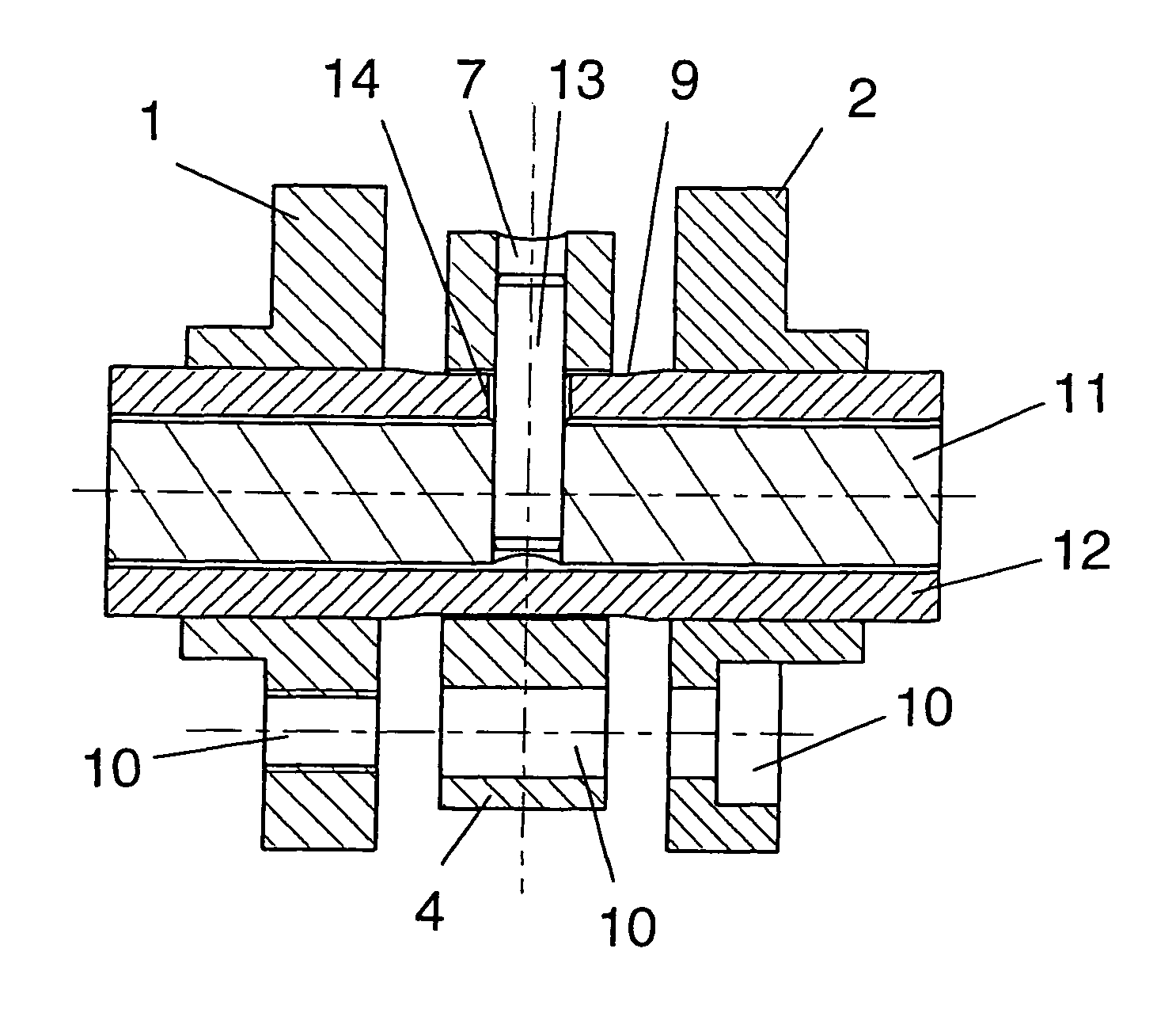
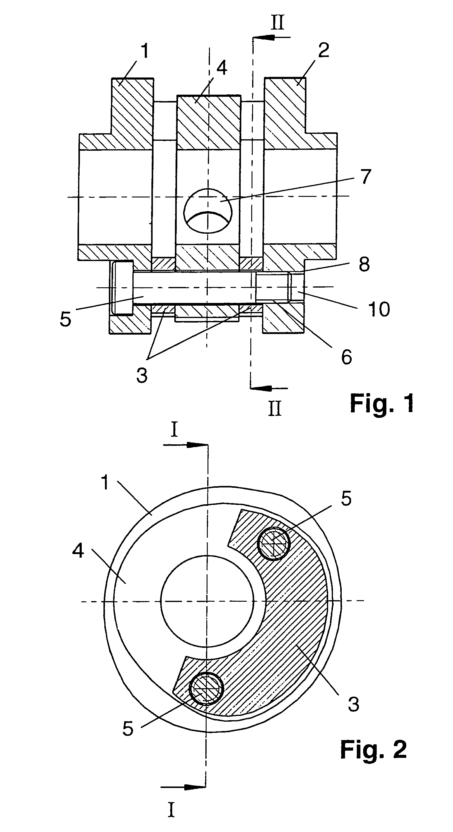
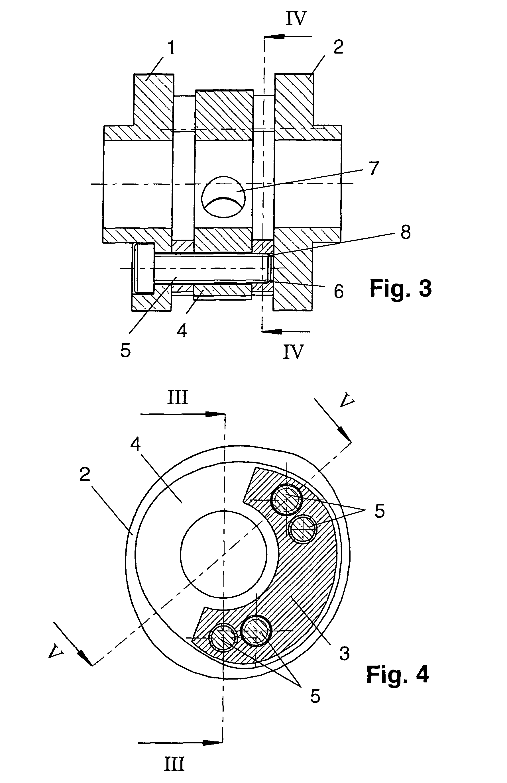
[0026]Two first cams 1, 2 are joined together in one machining module, each first cam being situated on an outer end axially. Between these two first cams 1, 2 there is a second cam 4 which is located at the center of the machining module and is spaced a distance axially away from the former via spacers 3 that are open at the circumference.

[0027]The total of three first and second cams 1, 2, 4 are linked together by two screws 5 that are approximately in opposition on the circumference. The two screws 5 are preferably designed as countersunk screws.

[0028]The cams 1, 2, 4 which are thus fixedly joined together in the machining module can be completely machined in this state, namely in particular with regard to their outside cam contours and their inside diameters.

[0029]The inside diameters of all the cams 1, 2, 4 are preferably selected to be the same in order to simplify machining.

[0030]The exemplary embodiment shown here concerns cams 1, 2, 4 for a camshaft having cams that are mut...


PUM

PropertyMeasurementUnit
diameteraaaaaaaaaa
distanceaaaaaaaaaa
tensionaaaaaaaaaa

Abstract

A camshaft has at least two completely machined individual cams fixedly mounted on a shaft in predetermined angular positions. The shaft includes an outside shaft and an inside shaft arranged concentrically in the former, and is to be manufactured in such a way that remachining of the joined camshaft is not necessary. This is by combining the individual cams even before they are mounted on a shaft and joining them to this shaft to form a machining module, such that the individual cams are combined in their mutual arrangement in relation to one another in which the cams are to be mounted on the finished camshaft. The final machining of the cams is performed within this machining nodule. When the cams are completely machined in this way, the cams are joined to the shaft of the camshaft within the machining module. This ensures that the desired mutual arrangement is maintained, i.e., that remachining is not necessary.

Description

CROSS REFERENCE TO RELATED APPLICATIONS[0001]Applicants claim priority under 35 U.S.C. §119 of German Application No. 10 2004 039 302.8 filed Aug. 13, 2004. Applicants also claim priority under 35 U.S.C. §365 of PCT / DE2005 / 001250 filed Jul. 15, 2005. The international application under PCT article 21(2) was not published in English.BACKGROUND OF THE INVENTION[0002]1. Field of the Invention[0003]The present invention relates to a method for manufacturing a camshaft according to the preamble of patent Claim 1.[0004]2. The Prior Art[0005]In the manufacture of camshafts in which the individual cams are not to be remachined after attaching and / or joining, one problem is how to join the individual cams accurately in the predetermined angular positions. Because of this difficulty, remachining is always necessary by grinding the cam contours after joining the individual cams or the tolerance limits of the cam positions must be determined by the joining process.[0006]U.S. Pat. No. 5,664,463 ...

Claims


Application Information

Patent Timeline
Patent Type & Authority Patents(United States)
IPC IPC(8): B21K1/12B23P21/00F01L1/04
CPCB23P15/00F01L1/047F01L1/34413F16H53/025Y10T29/49895F01L2001/0473Y10T74/2101Y10T29/4984Y10T29/49904Y10T29/49293Y10T29/49865Y10T29/49995Y10T29/49899Y10T29/49286B23P2700/02
Inventor FRITZ, OLIVERHENTSCHEL, TILOHOFFMANN, HERMANNLECHNER, MARTIN
Owner MAHLE VENTILRIEB
Why Eureka
Try Eureka