Eureka AIR delivers breakthrough ideas for toughest innovation challenges, trusted by R&D personnel around the world.

Motor control method and system based on hall sensor

A hall sensor, motor control technology, applied in control system, vector control system, motor generator control, etc., can solve problems such as angle error

Active Publication Date: 2019-07-26
ZHEJIANG GEELY HLDG GRP CO LTD +1
View PDF8 Cites 4 Cited by
  • Summary
  • Abstract
  • Description
  • Claims
  • Application Information

AI Technical Summary

Problems solved by technology

[0004] An object of the present invention is to provide a motor control method based on a Hall sensor to solve the problem that the calculated angle will have a large error due to a Hall sensor failure

Method used


Image

  • Motor control method and system based on hall sensor
  • Motor control method and system based on hall sensor
  • Motor control method and system based on hall sensor

Examples


Embodiment Construction

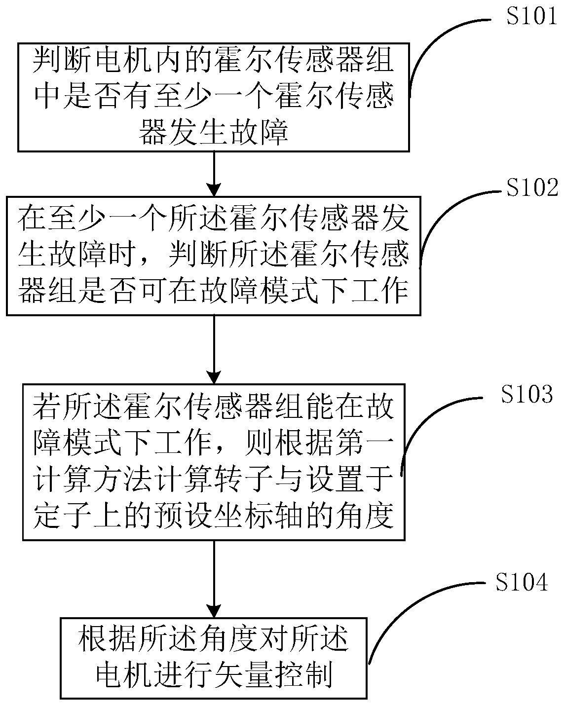
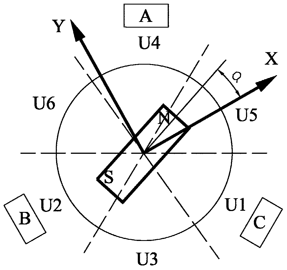
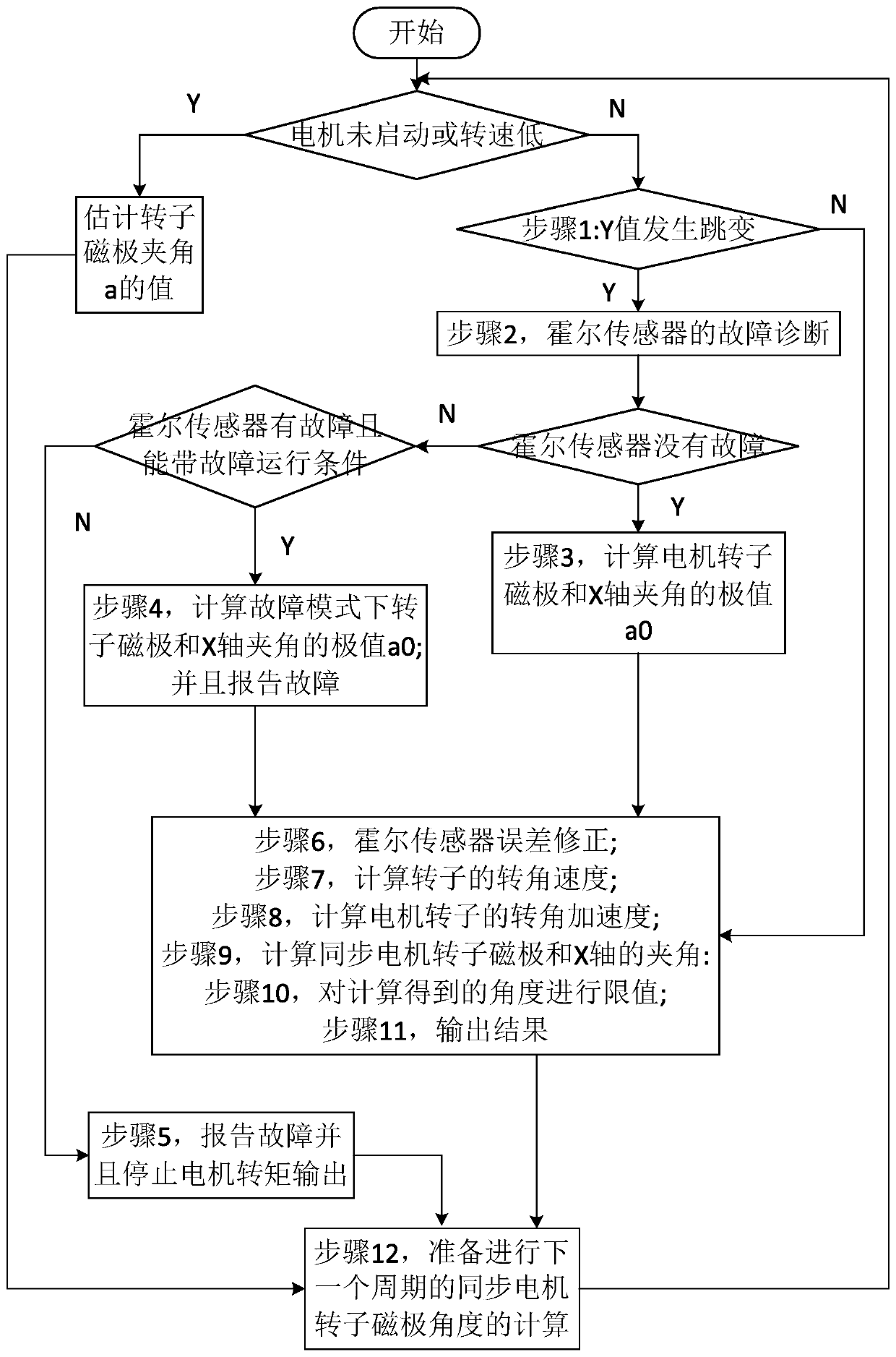
[0065] figure 1 is a schematic flowchart of a Hall sensor-based motor control method according to an embodiment of the present invention. figure 2 It is a schematic structural diagram of a Hall sensor group arranged on a motor according to an embodiment of the present invention. image 3 is a schematic flowchart of a Hall sensor-based motor control method according to another embodiment of the present invention. Figure 4 yes figure 2 A plot of the output signal for a properly functioning Hall sensor group is shown. Figure 5 It is the output signal diagram when the C sensor in the Hall sensor group shown in 2 fails. Refer below Figure 1 to Figure 5 The motor control method and system based on the Hall sensor according to the embodiment of the present invention will be described.

[0066] Such as figure 1 As shown, the Hall sensor-based motor control method of the present invention includes:

[0067] Step S101, judging whether at least one Hall sensor in the Hall sen...


PUM


Abstract

The invention provides a motor control method and system based on a hall sensor, and relates to the field of motors. In the motor control method based on the hall sensor, after a motor is operated, firstly, whether at least one hall sensor in a hall sensor group in the motor breaks down or not is judged; and if at least one hall sensor breaks down, then whether the hall sensor group can work in afault mode or not is judged. If the hall sensor group can work in the fault mode, the angle of a rotor and a preset coordinate axis arranged on a stator is calculated according to a first calculationmethod; and finally, vector control is carried out on the motor according to the angle. By adopting the method, when the motor operates, the hall sensor is firstly subjected to fault diagnosis, so that it is ensured that the calculated angle position is accurate and credible. Meanwhile, when the hall sensor breaks down severely, the motor is forbidden to run, so that the safety of the vehicle is ensured.

Description

technical field [0001] The invention relates to the field of motors, in particular to a Hall sensor-based motor control method and system. Background technique [0002] The back electromotive force waveform of the permanent magnet synchronous motor is partly different from the trapezoidal wave of the brushless DC motor, but a sine wave. If a square wave voltage is used to control the motor, the square wave control voltage and the sine wave back electromotive force will distort the current waveform of the motor, resulting in output torque fluctuations. Therefore, the control voltage of the permanent magnet synchronous motor needs to use vector control, which requires very accurate knowledge of the position of the rotor pole relative to the stator winding. Usually, the permanent magnet synchronous motor of new energy vehicles uses a resolver to obtain the accurate position of the rotor magnetic field of the motor, but the cost of the resolver is very high. [0003] In the pr...

Claims


Application Information

Patent Timeline
IPC IPC(8): H02P21/18
CPCH02P21/18
Inventor 陈刚
Owner ZHEJIANG GEELY HLDG GRP CO LTD
Why Eureka
Eureka Blog
Learn More