Swiveling device for a swiveling C-arm of an X-ray unit

a technology of x-ray unit and c-arm, which is applied in the direction of screen tubes, image-conversion/image-amplification tubes, gearing, etc., can solve the problems of requiring a certain dexterity and complicated c-arm adjustment when determined the treatment site, and achieve the effect of improving access to the treatment si

Active Publication Date: 2014-02-25
RICHARD WOLF GMBH
View PDF22 Cites 4 Cited by
  • Summary
  • Abstract
  • Description
  • Claims
  • Application Information

AI Technical Summary

Benefits of technology

[0006]The swiveling device according to a preferred embodiment of the present invention for a preferably laterally swiveling C-arm of an X-ray unit includes a motorized drive unit as well as an adapter that is attached to the C-arm concentrically with the swiveling axis thereof. The adapter may be used to connect the C-arm to the drive unit in driving manner, that is to say the drive unit may be connected to the C-arm via the adapter in such manner that the motion of a motorized drive of the drive unit, which is preferably realized as a rotary drive, may be transferred to the C-arm. In this case, it is expedient if the drive unit is mounted to a part of the X-ray unit that is constructed in fixed manner, unlike the C-arm, so that the C-arm is able to swivel relative to this part. The drive may be a direct drive, in which the rotating motion of the drive shaft of a drive motor is transferred directly to the C-arm. However, the torque required to swivel the C-arm is preferably transferred to C-arm via a gearbox fitted ahead of the C-arm, wherein a gearbox that reduces the rotating speed of the drive motor enables particularly precise angular positioning of the C-arm.
[0008]The angular position encoder may be a sensor of such kind with which for example the angular position of the C-arm may be determined directly and without contact. However, it is preferably intended to use an angular position encoder that is arranged so as to record the angle of rotation of a part of the drive unit that may be connected to the adapter. This is advantageous in that the angular position encoder may then be disposed in a housing of the drive unit for protection.
[0010]In a further advantageous embodiment, the drive shaft of the motorized drive of the drive unit in the swiveling device according to the present invention, which is preferably the drive shaft of an electric motor, may be coupled to the part of the drive unit that may be connected to the adapter in a joining manner via a worm drive. If a worm drive is used, it is possible to align the axis of rotation of the motor drive shaft and the axis of rotation of the part of the drive unit that may be connected to the adapter normally relative to one another so that the drive unit may be constructed in relatively compact manner. Moreover, it is possible to achieve quite large speed reductions with a worm drive, which in turn enables particularly good positional accuracy of the C-arm.
[0012]In an further advantageous design of the swiveling device according to the present invention, it may also be constructed so as to enable the C-arm to be swiveled rapidly by hand, thereby improving access to the treatment site. To this end, a friction clutch may be provided and arranged between the drive unit of the drive motor and the adapter. This friction clutch enables the drive train of the drive unit between the adapter and the drive motor to be disengaged temporarily by swiveling the C-arm manually. The part that may be connected to the adapter preferably forms a part of the friction clutch for this purpose.

Problems solved by technology

The precise adjustment of the C-arm when determined the treatment site is relatively complicated and requires a certain dexterity.

Method used


Image

  • Swiveling device for a swiveling C-arm of an X-ray unit
  • Swiveling device for a swiveling C-arm of an X-ray unit
  • Swiveling device for a swiveling C-arm of an X-ray unit

Examples


Embodiment Construction

[0020]Certain terminology is used in the following description for convenience only and is not limiting. The words “bottom” and “top” designate directions in the drawings to which reference is made. Unless specifically set forth herein, the terms “a,”“an” and “the” are not limited to one element, but instead should be read as meaning “at least one.” The terminology includes the words noted above, derivatives thereof and words of similar import.

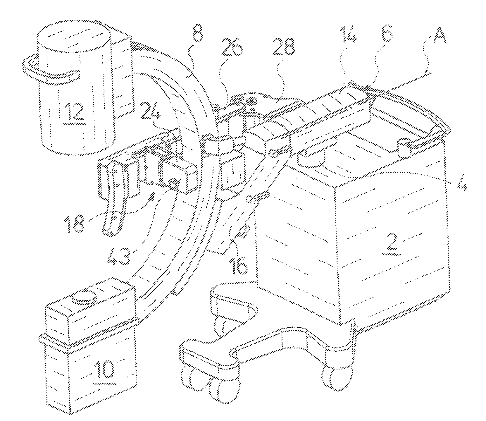
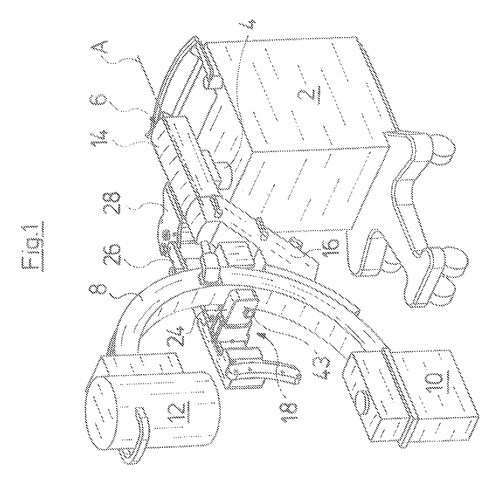
[0021]Referring to the drawings in detail, wherein like numerals indicate like elements throughout the several views, the X-ray unit shown in FIG. 1 is a known device having an base cart 2, from the top of which an extendable mounting column 4 protrudes vertically. A C-arm 8 of the X-ray unit is attached in height-adjustable manner to mounting column 4 via an angled arm 6. An X-ray source 10 is attached to the bottom end of C-arm 8, and an image amplifier 12 is arranged at the bottom end thereof, both in the usual manner.

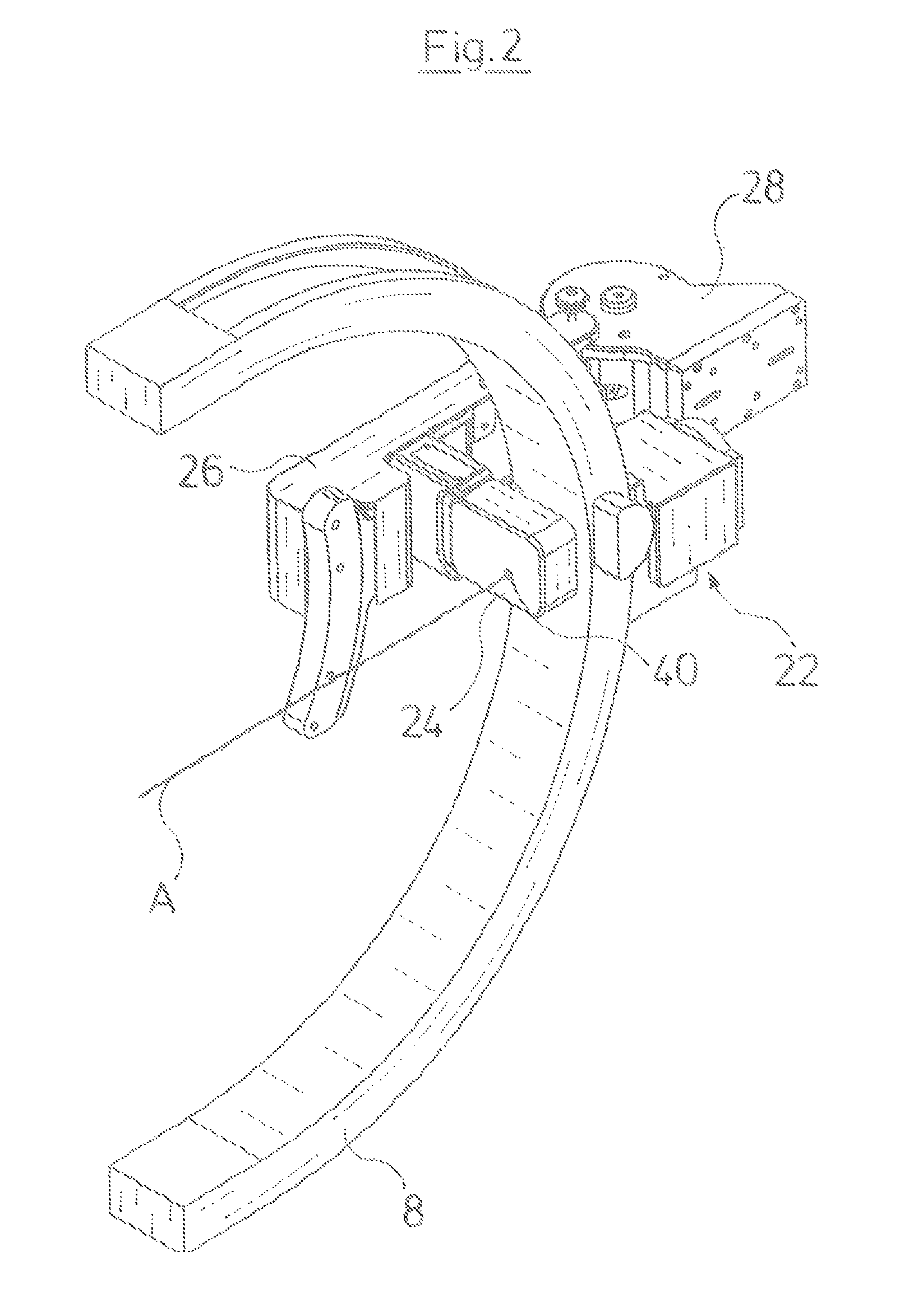
[0022]Arm 6, to which ...


PUM


Abstract

A swiveling device for a swiveling C-arm of an X-ray unit includes a motorized drive unit and an adapter removably attachable to the C-arm concentrically with a swiveling axis thereof. The adapter connects the C-arm to the drive unit in driving manner. The swiveling device also includes an angular position encoder for recording the swivel angle of the C-arm.

Description

BACKGROUND OF THE INVENTION[0001]The present invention relates generally to a swiveling device for a swiveling C-arm of an X-ray unit.[0002]Diagnostic X-ray units are used in conjunction with treatment devices to determine the treatment site inside the body precisely before treatment begins, and during treatment as necessary. For example, they are used in the extracorporeal treatment of concretions such as kidney and urinary calculus. In such procedures, the focus of the ultrasonic source to be used to disintegrate the concretion is aligned precisely with the treatment site that has been determined previously with the aid of the X-ray unit. To determine the treatment site, the patient who is to undergo the treatment is first roentgenized with the X-ray unit in two different planes. To do this, an X-ray unit C-arm is used, on which an X-ray source and an image amplifier are arranged directly opposite one another, and typically constructed in swiveling manner. Thus, the patient may be...

Claims


Application Information

Patent Timeline
Patent Type & Authority Patents(United States)
IPC IPC(8): F16H19/06F16H19/02
CPCA61B6/4441A61B6/4405A61B6/547Y10T74/18152Y10T74/18056Y10T74/18088
Inventor MULLER, KLAUSWEISERT, WILLI
Owner RICHARD WOLF GMBH
Why Eureka
Try Eureka