Determining the rotor angle of a synchronous machine at standstill with the aid of iterative test pulses

a technology of synchronous machines and iterative test pulses, which is applied in the direction of electronic commutators, motor/generator/converter stoppers, dynamo-electric converter control, etc., can solve the problems of affecting the accuracy of synchronous machines, etc., to achieve the effect of simple evaluation mechanisms and small investmen

Active Publication Date: 2013-10-01
ROBERT BOSCH GMBH
View PDF15 Cites 4 Cited by
  • Summary
  • Abstract
  • Description
  • Claims
  • Application Information

AI Technical Summary

Benefits of technology

[0010]It is, therefore, an object of the present invention to devise a mechanism for precisely sensing the absolute angular position for electric motors that is able to be realized with little outlay for electrical components and using simple evaluation mechanisms.
[0011]The present invention permits a precise absolute angle determination for electric machines, in particular, for synchronous machines, without entailing additional components and through the use of a substantially simplified calculation method. The method may be implemented using low-cost components since it only requires a minimal computing capacity, achieves a high degree of precision, is influenced only slightly by external stray magnetic fields since a multiplicity of measurements are taken, and renders possible an angular position resolution of virtually any given precision. Already existing devices, which are connected to the electric machine, may be used both for the processing of the measuring method, as well as for generating and supplying the measuring pulses. Thus, the present invention makes it possible to precisely sense the angular position of the rotor at standstill, the maximum possible torque being attainable during the run-up process, already after a short measuring period. The method entails low costs, minimal spatial requirements, and is characterized by substantial ruggedness. In one preferred specific embodiment, the present invention also permits the unique acquisition of the angular position with respect to a complete 360° rotation without ambiguity in the 180° orientation. In particular, the method does not require any costly interpolation or interpretation of the measured values, but may be implemented exclusively using simple comparison processes and basic calculating operations. In particular, the present invention may be carried out using comparators and devices which generate a mean angular value, for example, as software that runs on a processor. In addition, the present invention may be realized using a hardwired circuit having a comparator, an adder circuit, and a device for halving a value.
[0013]In addition, the saturation prevailing in the angular direction in question plays a role, the magnetic permeability decreasing with increasing saturation. In other words, an additional magnetic field results in an only slight increase in the magnetic flux in the material when the material has already undergone a strong premagnetization. For example, the premagnetization may be effected by an excitation coil (or by a permanent magnet or a combination thereof) of the rotor, the additional magnetic field component being externally predefined by the stator which, depending on the orientation, is either added to the premagnetization or reduces the same. If the externally applied magnetic field reduces the flux within the material, then a greater inductance results than in the opposite direction when the external magnetic field is added to the rotor's magnetic field (which relates to the premagnetization). Thus, the rotor emitting a magnetization pulse in two opposite directions makes it possible for its half-space orientation (or generally the north-south orientation of a pole pair of any given number of pole pairs) to be precisely recorded.
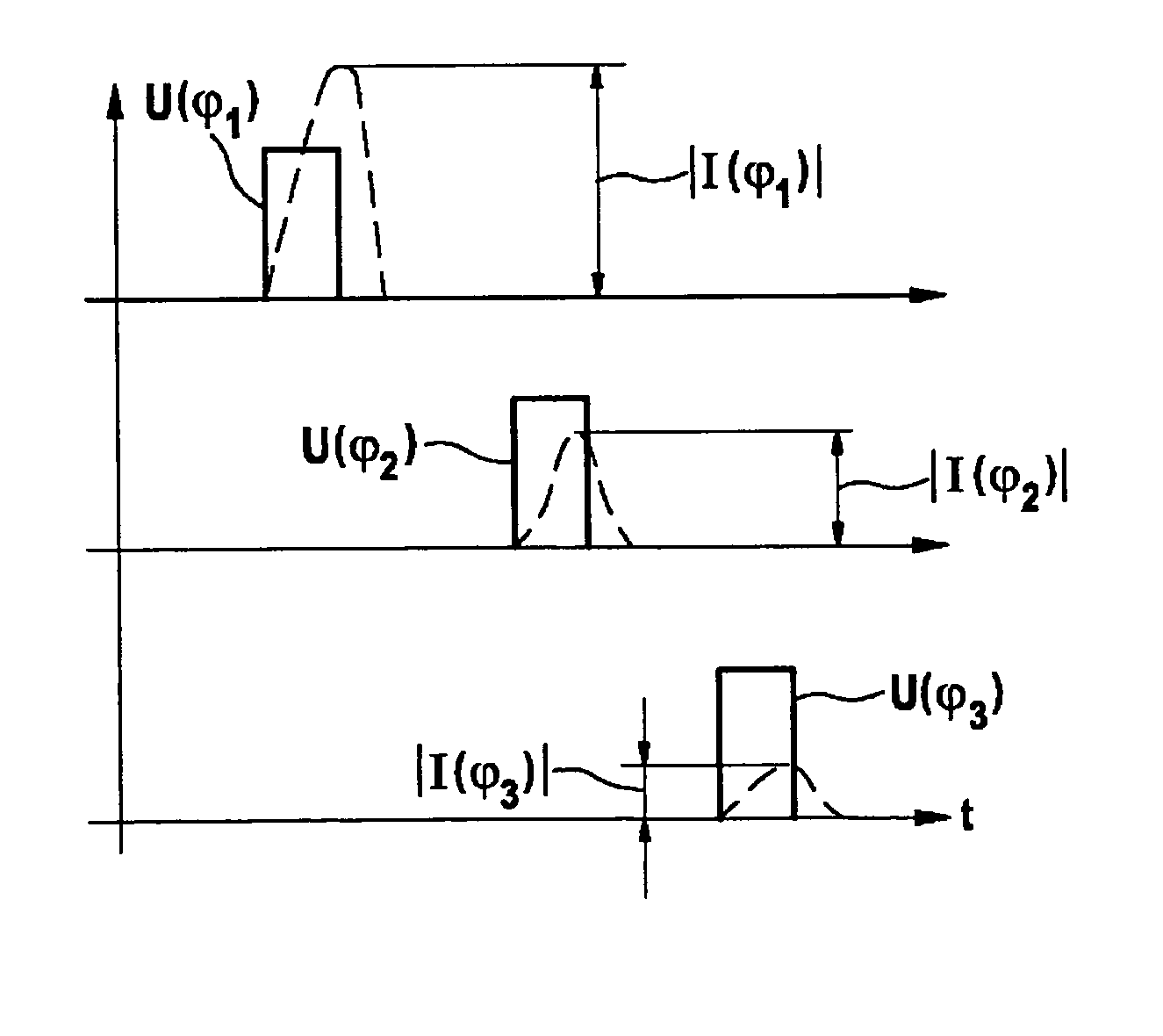
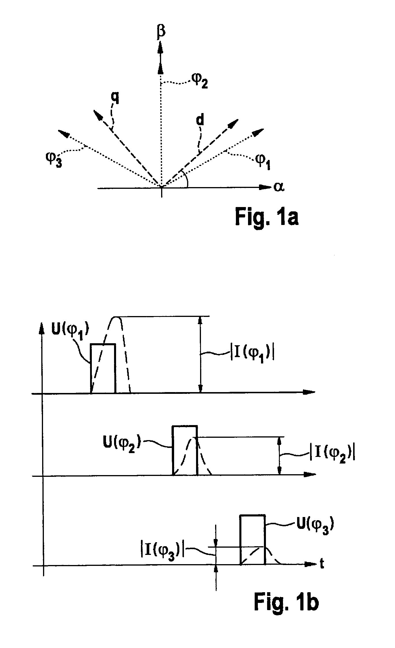
[0031]To resolve the 180° ambiguity, an absolute orientation step is preferably performed, where measurements are taken along angular directions that oppose one another by 180° or, in the case of a rotor having more than two poles, in directions that correspond to a multiple of 360° / p, p being the number of magnetic poles of the rotor. In this case, orientation peak values of the current pulse that was generated by the orientation magnetic fields, are recorded, and the lowest or highest orientation peak value and the corresponding angular direction of the two or of all orientation peak values are recorded. The corresponding angular direction resides in an absolute orientation angular sector that is obtained by dividing an entire circumference into p angular sectors. Thus, in the case of a rotor having a north and a south pole, by comparing two different angular directions that are offset by 180°, respectively the peak values thereof, it is possible to discern the hemisphere (i.e., half angular extent) in which the rotor is oriented. In the case of rotors having an excitation winding, the greater of the two peak values corresponds to the hemisphere into which the magnetic north pole points. The rotor is preferably excited during the absolute orientation step; in the case of excitation coil-excited motors, this being effected by energizing the excitation winding.

Problems solved by technology

Under certain circumstances, a deviation of only a few degrees can result in a very pronounced difference with respect to the torque.
The use of separate sensors entails additional space, additional costs, separate supply leads, and additional manufacturing steps, etc.
Moreover, additional components have the inherent risk of generally being associated with additional sources of error.
On the one hand, the method is costly since the angular position is based on the combination of a multiplicity of various rise times that are indicative of the particular saturation, and, on the other hand, since the resolution is defined by the angular offset of two different stator windings, i.e., 60°, for example.
In addition, inaccuracies in the position can result at locations where the inductance only changes slightly with the angle, i.e., at + / −90°, for example.
Therefore, the absolute angle sensing methods mentioned above in the context of stationary electric motors are associated, on the one hand, with additional components, or they entail a costly calculation and, at the same time, are prone to a reduced accuracy and a high fault rate due to external stray fields.
In particular, interpolation-based angle acquisitions require a considerable outlay for complex calculations; even in the case of minor measurement errors, the interpolation also leading to substantial angular errors.

Method used


Image

  • Determining the rotor angle of a synchronous machine at standstill with the aid of iterative test pulses
  • Determining the rotor angle of a synchronous machine at standstill with the aid of iterative test pulses
  • Determining the rotor angle of a synchronous machine at standstill with the aid of iterative test pulses

Examples


Embodiment Construction

[0042]FIG. 1a shows the initialization of the method according to the present invention with reference to a circuit diagram that is based on a rotor having a north and a south pole. The main magnetization direction, thus the field lines of the magnetic field produced by an excitation coil, extends along the axis characterized by d. The q-axis extends orthogonally thereto and corresponds to the transversal axis which is orthogonal to longitudinal axis d, the q-axis extending orthogonally to the field lines of the excitation magnetic field. Initially, the angular directions that are each offset by 60° from one another are scanned in accordance with the active scanning method, i.e., in that a voltage pulse is emitted in each of directions φ1, φ2 and φ3. In other words, three different voltage pulses are transmitted to the stator, which, as a result, generates three different magnetic fields in directions φ1, φ2 and φ3. The corresponding current characteristics are recorded.

[0043]In FIG...


PUM


Abstract

A method for determining the angular position of a synchronous machine having a magnetically anisotropic rotor includes an (m) iteration stage and an (n) iteration stage. The (m) iteration stage encompasses: generating an (m) magnetic field of an (m) angular direction and acquiring an (m) peak value of the current pulse generated by the (m) voltage pulse; and providing at least two further (m+i) peak values in different (m+i) angular directions that differ from the (m) angular direction. The (n) iteration stage includes: ascertaining the angular directions (n) and (n+1) in which the two highest or the two lowest peak values from a peak value group occur; and providing an (n) angular direction, which resides between the (n+1) angular direction and the (n+2) angular direction, as an angular position output.

Description

BACKGROUND OF THE INVENTION[0001]1. Field of the Invention[0002]The present invention is directed to angle-sensing mechanisms for electric motors and, in particular, for synchronous machines.[0003]2. Description of Related Art[0004]Electric motors are used for a multiplicity of applications; depending on the particular use, not only the speed itself, but also the rotor position being relevant. Sensing the rotor position is particularly relevant when switching on electric machines since, relative to the stator's magnetic field, the rotor position directly and significantly influences the absolute value and sign of the torque generated. Sensing the correct angle of the rotor position is particularly relevant for the operation of synchronous machines where essentially no difference in speed (“slip”) is provided between the rotor and the stator. Under certain circumstances, a deviation of only a few degrees can result in a very pronounced difference with respect to the torque. In synchr...

Claims


Application Information

Patent Timeline
Patent Type & Authority Patents(United States)
IPC IPC(8): H02P6/18H02P6/20
CPCH02P1/46H02P6/185H02P6/20
Inventor VOLLMER, ULRICH
Owner ROBERT BOSCH GMBH
Why Eureka
Try Eureka