Exhaust heat recovery system

a heat recovery system and exhaust gas technology, applied in the direction of machines/engines, combustion-air/fuel-air treatment, lighting and heating apparatus, etc., can solve the problem of difficult to effectively use the exhaust heat of the engine, and achieve the effect of effectively using the heat recovered from the exhaust gas

Inactive Publication Date: 2010-12-07
DENSO CORP
View PDF10 Cites 12 Cited by
  • Summary
  • Abstract
  • Description
  • Claims
  • Application Information

AI Technical Summary

Benefits of technology

[0007]In view of the foregoing problems, it is an object of the present invention to effectively use heat recovered from exhaust gas of an internal combustion engine.

Problems solved by technology

However, in the above exhaust heat recovery system, the heat recovered in the exhaust heat of the engine is only used for heating air in the air conditioner in the winter, and thereby it is difficult to effectively use the exhaust heat from the engine.

Method used


Image

  • Exhaust heat recovery system
  • Exhaust heat recovery system
  • Exhaust heat recovery system

Examples


Embodiment Construction

[0016]An embodiment of the present invention will be now described with reference to FIGS. 1 to 2C.

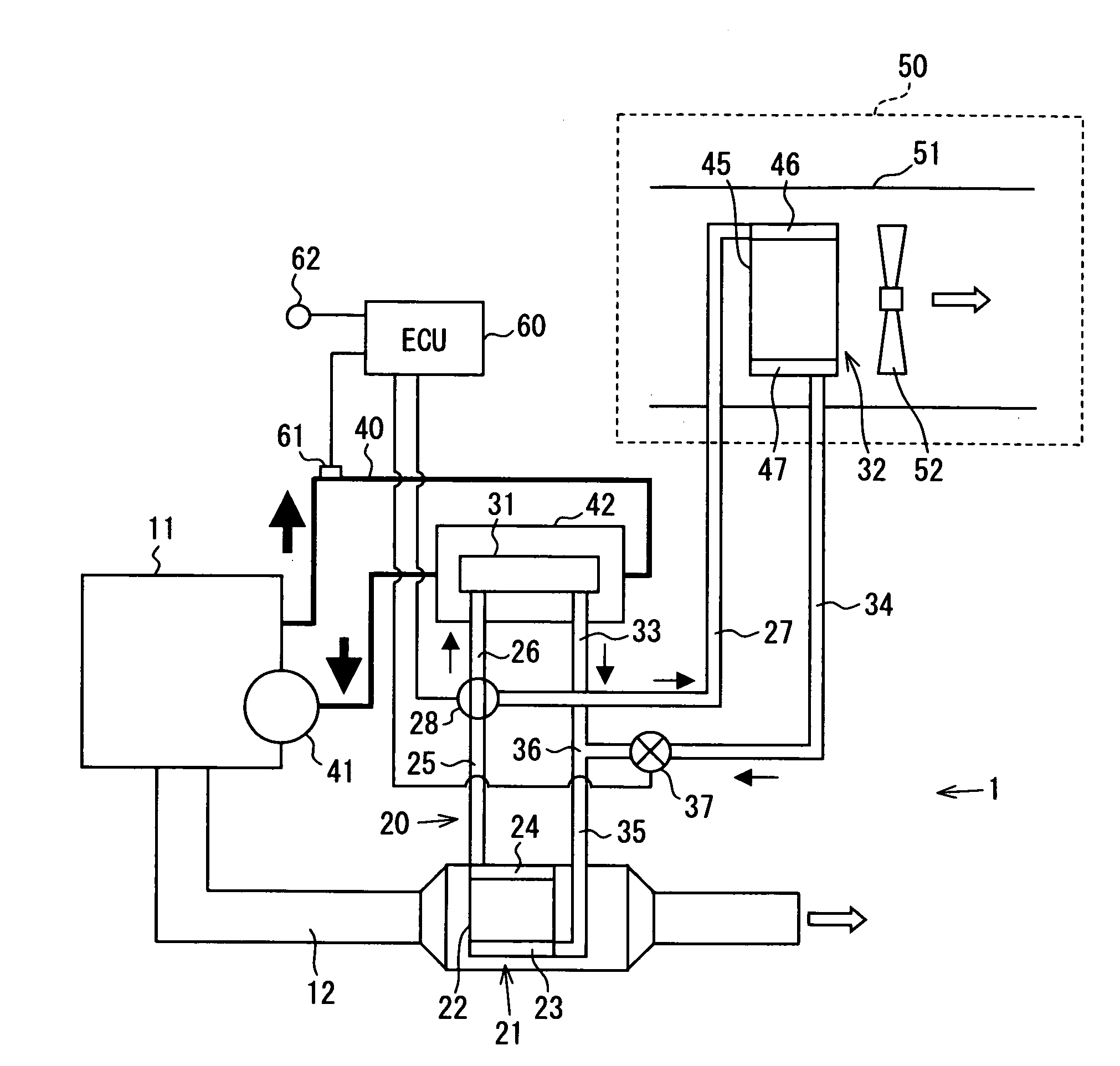
[0017]As shown in FIG. 1, an exhaust heat recovery system 1 includes an engine (internal combustion engine) 11 used as a driving source for a vehicle running, an exhaust gas pipe 12 trough which exhaust gas discharged from the engine 11 flows.

[0018]The exhaust heat recovery system 1 is provided with a heat pipe 20 for recovering exhaust heat from the engine 11. For example, the heat pipe 20 is a loop-type heat pipe in which first and second condensing portions 31, 32 are connected to the evaporation portion 21 in parallel with respect to an evaporation portion 21. The first and second condensing portions 31, 32 are located above the evaporation portion 21 and are coupled to the evaporation portion 21 so as to form a closed circuit in which a working fluid circulates.

[0019]The heat pipe 20 has an inlet port (not shown) from which the working fluid is introduced. The working fluid is int...


PUM


Abstract

In an exhaust heat recovery system for an internal combustion engine, a heat pipe includes an evaporation portion in which a working fluid is heated and evaporated by heat exchange with exhaust heat from the internal combustion engine, a plurality of condensing portions in which the working fluid from the evaporation portion is cooled and condensed by heat exchange with respective subjects to be heated, and connection piping through which the condensing portions are connected to the evaporation portion in parallel with respect to the evaporation portion so as to form a closed circuit. Furthermore, a switching portion is located to switch a flow of the working fluid from the evaporation portion to any one between the condensing portions.

Description

CROSS REFERENCE TO RELATED APPLICATION[0001]This application is based on Japanese Patent Application No. 2007-029569 filed on Feb. 8, 2007, the contents of which are incorporated herein by reference in its entirety.BACKGROUND OF THE INVENTION[0002]1. Field of the Invention[0003]The present invention relates to an exhaust heat recovery system for recovering exhaust heat discharged from an internal combustion engine.[0004]2. Description of the Related Art[0005]In an exhaust heat recovery system described in JP-A-3-128719, an auxiliary heating is performed for an air conditioner by using exhaust heat from an engine. The exhaust heat recovery system is provided with a heat pipe that includes an evaporation portion (heat receiving portion) at one end, and a condensing portion (heat radiating portion) at the other end. The evaporation portion is located in an exhaust gas passage of the engine, and the condensing portion is located adjacent a heater core in an air conditioning case of the ...

Claims


Application Information

Patent Timeline
Patent Type & Authority Patents(United States)
IPC IPC(8): F01N3/02
CPCF01N5/02F28D15/0266F28D15/06F28D21/0003Y02T10/16Y02T10/12
Inventor MIYAGAWA, MASASHIYAMANAKA, YASUTOSHISUZUKI, TAKAHISABAN, KOICHI
Owner DENSO CORP
Why Eureka
Try Eureka