
Method and system for observing a subject at a first location based upon quantum properties measured at a second location

a quantum property and subject technology, applied in the field of quantum imaging, can solve the problems of hampered efforts to develop reflective ghost imaging systems, unable to theoretically understand ghost imaging, and unable to reach the theoretical limits of image resolution

Inactive Publication Date: 2010-12-07
US SEC THE ARMY THE
View PDF15 Cites 29 Cited by
  • Summary
  • Abstract
  • Description
  • Claims
  • Application Information

AI Technical Summary

Benefits of technology

"The present invention relates to a method for measuring the interaction between a target and a photon. The method involves generating an entangled photon pair and sending one of the photons along a target path while the other photon remains in a reference path. The target affects the photon in the target path, resulting in a measurement of the photon's properties. By measuring the time of flight or the distance traveled by the photon, the interaction between the target and the photon can be determined. The method can be used to detect and identify objects or targets in space using a variety of photon properties such as color, polarization, and spin. The invention provides a more accurate and reliable way to measure the interaction between a target and a photon."

Problems solved by technology

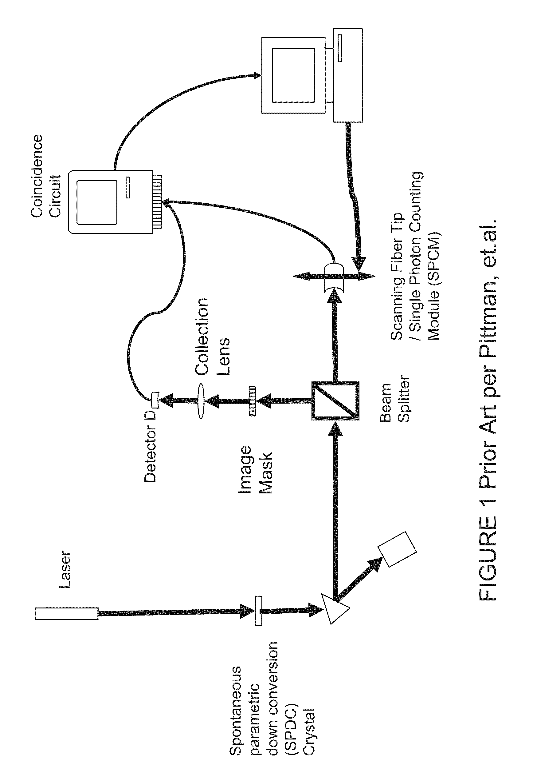
Conventional imaging techniques have, to a large extent, arrived at the theoretical limits of image resolution owing to wavelength-limited resolution, optical element distortions, and the reflective interaction between photons and an object to be imaged.
The ongoing lack of theoretical understanding of ghost imaging has hampered efforts to develop reflective ghost imaging systems for practical field uses in such fields as satellite, field, medical and research imaging.
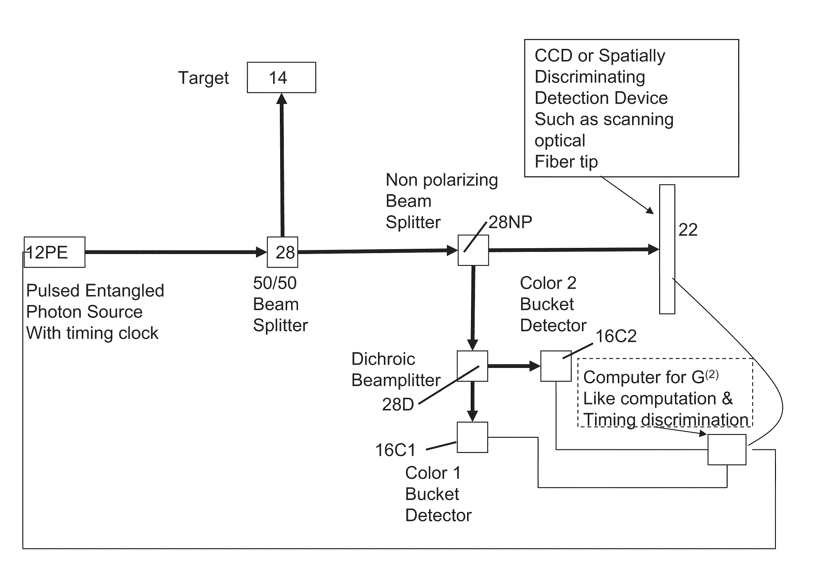
Moreover, there exists a need for a system using ghost image where feedback or measurement is not possible at the target area.

Method used


Image

  • Method and system for observing a subject at a first location based upon quantum properties measured at a second location
  • Method and system for observing a subject at a first location based upon quantum properties measured at a second location
  • Method and system for observing a subject at a first location based upon quantum properties measured at a second location

Examples


Embodiment Construction

[0048]The present invention now will be described more fully hereinafter with reference to the accompanying drawings, in which embodiments of the invention are shown. However, this invention should not be construed as limited to the embodiments set forth herein. Rather, these embodiments are provided so that this disclosure will be thorough and complete, and will fully convey the scope of the invention to those skilled in the art. In the drawings, the dimensions of objects and regions may be exaggerated for clarity. Like numbers refer to like elements throughout. As used herein the term “and / or” includes any and all combinations of one or more of the associated listed items.

[0049]The terminology used herein is for the purpose of describing particular embodiments only and is not intended to limit the full scope of the invention. As used herein, the singular forms “a”, “an” and “the” are intended to include the plural forms as well, unless the context clearly indicates otherwise. It w...


PUM


Abstract

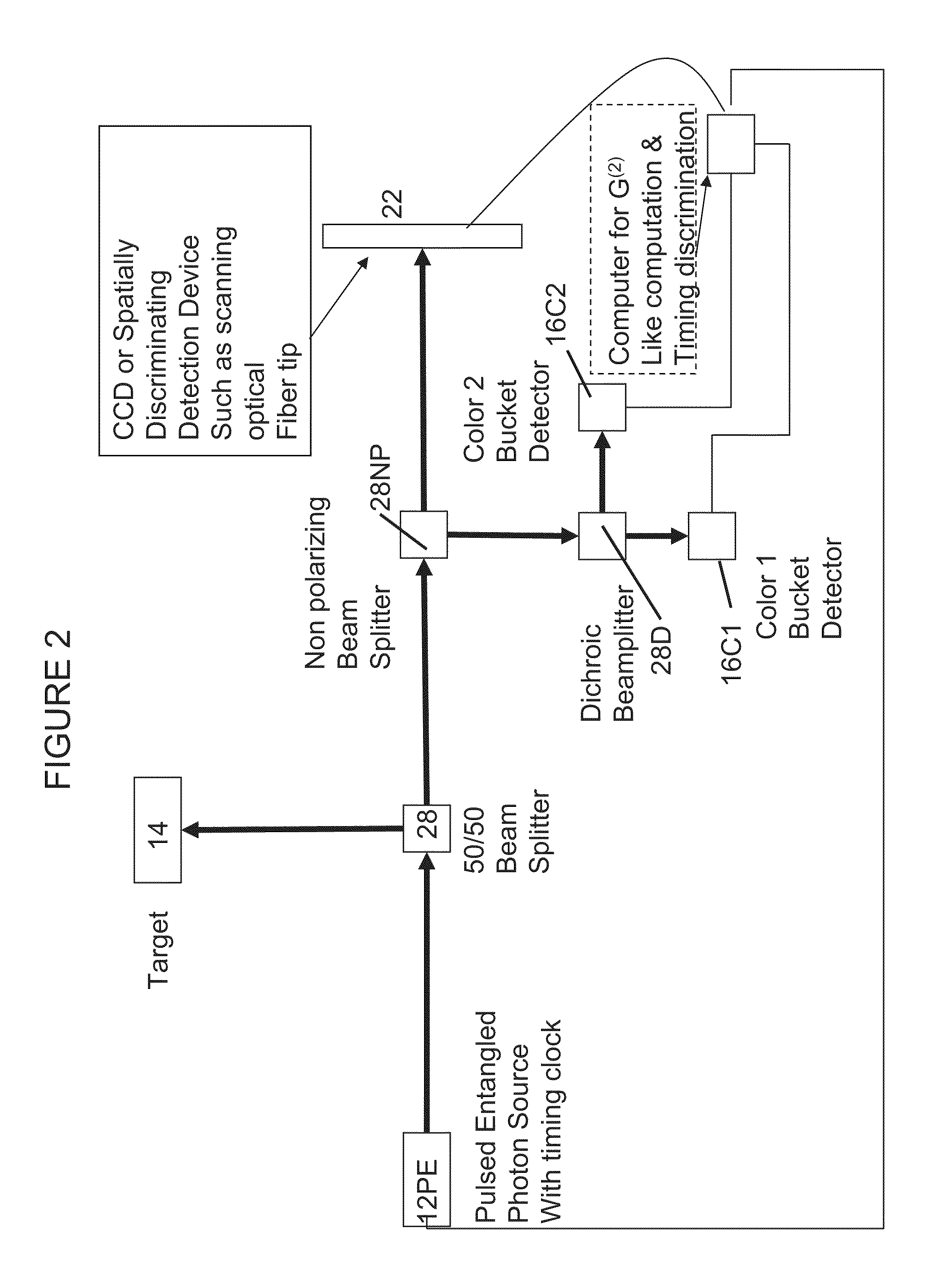
A preferred embodiment comprises a method and system for (a) detecting objects or targets which may or may not be nonreflective to electromagnetic radiation, and / or (b) generating an image of a subject or area, comprising generating an entangled photon pair beam; splitting the entangled photon pair beam into first and second parts; the first parts being directed in a first direction towards a first location, and the second parts being received into a measuring device; measuring the physical characteristics of the conjugate second parts to determine whether or not the first parts have encountered the presence or absence of an object at the first location in combination with the time that the first part takes to enter the first location. The method and system incorporate a photon beam in a reference path that never directly interacts with the object yet is determinative of presence or absence of an object at the first location. The splitting of the entangled photon pair beam occurs prior to the first parts being absorbed by said object, and the measuring of the characteristics of the conjugates occurs subsequent to the splitting of the entangled photon beam.

Description

CROSS-REFERENCE TO RELATED APPLICATIONS[0001]This application claims priority of U.S. patent application Ser. No. 12 / 330,401, filed Dec. 8, 2008, which claims priority to U.S. Provisional Patent Application Ser. No. 60 / 993,792 filed Dec. 6, 2008; which are both incorporated by reference herein. This application also claims priority to U.S. patent application Ser. No. 10 / 900,351, filed on Jul. 28, 2004, which in turn claims priority to U.S. Provisional Application No. 60 / 493,107, filed Aug. 6, 2003, which are both incorporated by reference herein.GOVERNMENT INTEREST[0002]The invention described herein may be manufactured, used, and licensed by or for the United States Government.FIELD OF THE INVENTION[0003]This invention relates in general to a process and apparatus for quantum imaging using entangled photon pairs and in particular to a process using the properties of quantum imaging to generate an image of an object via correlations between photons or quantum particles reflected off...

Claims


Application Information

Patent Timeline
Patent Type & Authority Patents(United States)
IPC IPC(8): H01J40/14
CPCH04L9/0858
Inventor MEYERS, RONALD EVERETTDEACON, KEITH SCOTT
Owner US SEC THE ARMY THE
Learn More