Hard disk bracket and electronic device employing the same

a technology of electronic devices and hard disks, applied in the field of electronic devices, can solve the problems of inconvenient assembly or disassembly of hard disks

Active Publication Date: 2010-12-07
CLOUD NETWORK TECH SINGAPORE PTE LTD
View PDF10 Cites 4 Cited by
  • Summary
  • Abstract
  • Description
  • Claims
  • Application Information

AI Technical Summary

Benefits of technology

[0012]The three limiting portions 142 align with the two supporting portions 144. In this embodiment, the fixing members 14 are integrally formed with the chassis 12. In each row of the fixing members 14, at least one of the three limiting portions 142 and at least one aligned of the two supporting portions 144 are integrally formed. An inverted U-shaped slot 15 surrounding each of the limiting portions 142 is integrally formed with and defined in the supporting portions 11, so that the limiting portions 142 have good resilience permitting the hard disk to be positioned in the hard disk bracket.
[0014]Each of the three limiting portions 142 includes a positioning pin 1422 projecting from an inner surface thereof, adjacent to a top free ends 1424 thereof, and received in a corresponding positioning hole 52 to fix the hard disk 50 in the hard disk bracket 10. A cross-section 1426 of each of the limiting portions 142 is trapeziform with a narrow top side edge, so that each of the top free ends 1424 of the limiting portions 142 can be deflect under an external force, and the positioning pins 1422 are easily inserted into or removed from the corresponding positioning holes 52 of the hard disk 50 when the hard disk 50 is attached to the hard disk bracket 10. Each supporting portion 144 includes a supporting plate 1442 projecting from an inner surface thereof and parallel to the chassis 12 to support the hard disk 50. Each supporting plate 1442 includes a positioning block 1444 projecting upwardly capable of being inserted into a corresponding recess 54 of the hard disk 50 to further fix the hard disk 50 in the hard disk bracket 10.
[0016]In the illustrated embodiment, the hard disk bracket 10 further includes a plurality elastic elements 40, such as springs, to protect the hard disk 50 from vibration, where some of the elastic elements 40 are respectively located between the limiting portions 142 and the side walls of the hard disk 50, and others are respectively located between the supporting plates 1442 and the bottom wall of the hard disk 50 after the hard disk 50 is attached to the hard disk bracket 10.

Problems solved by technology

A frequently used hard disk is directly fixed in an enclosure of the electronic device by screws, resulting in inconvenience of assembly or disassembly of the hard disk.

Method used


Image

  • Hard disk bracket and electronic device employing the same
  • Hard disk bracket and electronic device employing the same
  • Hard disk bracket and electronic device employing the same

Examples


Embodiment Construction

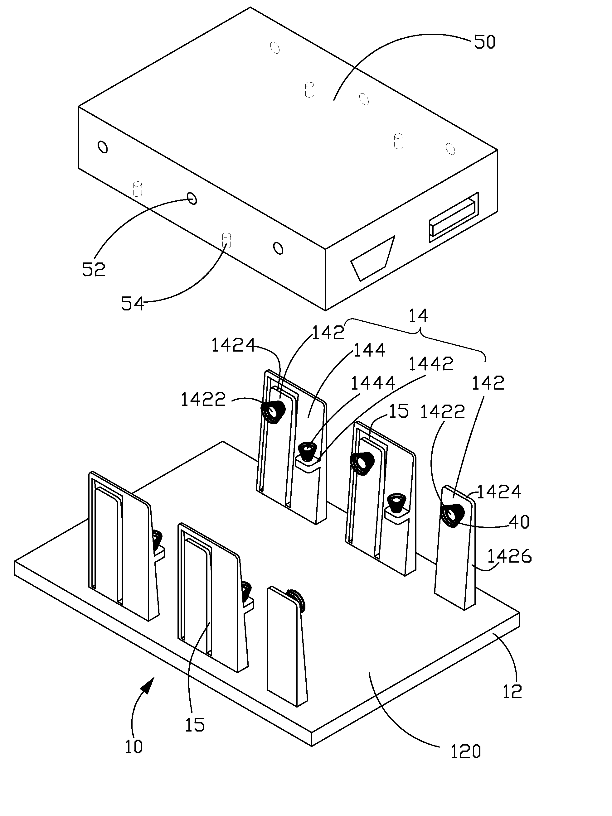
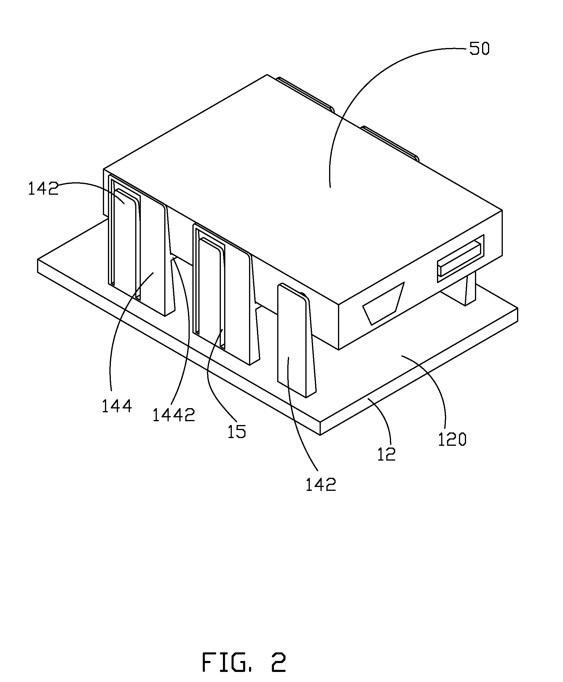
[0009]Referring to FIG. 1-FIG. 3, a hard disk bracket 10 is used for fixing a hard disk 50. The hard disk 50 defines a plurality of positioning holes 52 in two opposite sidewalls thereof and a plurality of recesses 54 in a bottom wall thereof.

[0010]The hard disk bracket 10 may be formed using an injection mold process to conserve parts costs, in one example. However, it may be understood by those of ordinary skill in the art that the hard disk bracket 10 may be formed using other techniques.

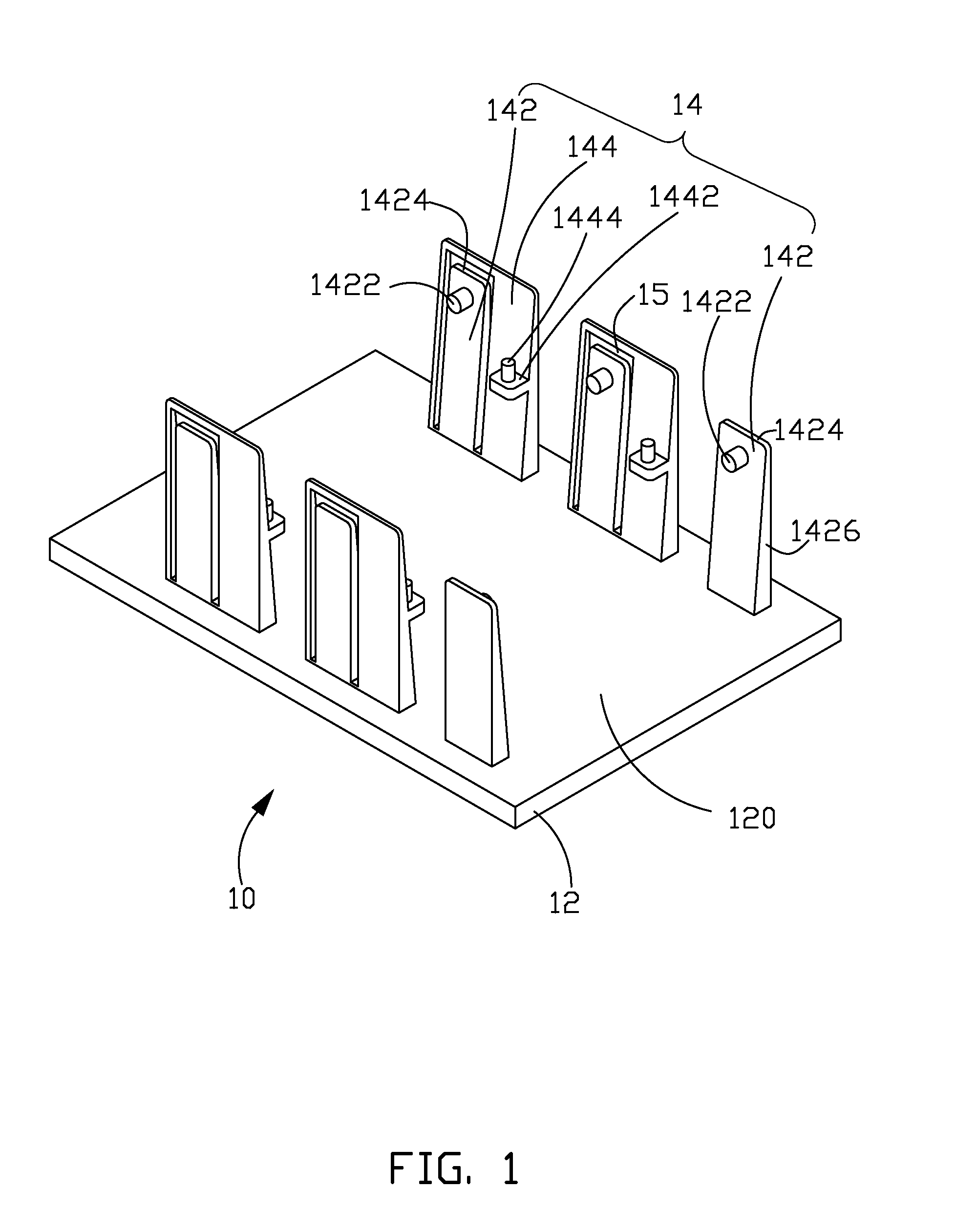
[0011]The hard disk bracket 10 includes a chassis 12 including a surface 120 and two substantially parallel rows of fixing members 14 projecting from the surface 120 of the chassis 12 spaced from each other and receiving the hard disk 50 therebetween. Each row of the fixing members 14 includes three limiting portions 142 and two supporting portion 144. Alternatively, one or more limiting portions 142 and supporting portions 144 can be utilized.

[0012]The three limiting portions 142 align with the ...


PUM


Abstract

A hard disk bracket for fixing a hard disk defining a plurality of positioning holes in two opposite sidewalls thereof includes a chassis and two substantially parallel rows of fixing members projecting from the chassis, spaced from each other, and receiving the hard disk therebetween. Each row of the fixing portion includes at least resilient two limiting portions each including a positioning pin received in the corresponding positioning hole to fix the hard disk and at least one supporting portion including a supporting plate parallel to the chassis to support the hard disk. The at least two limiting portions align with the at least one supporting portion. A distance between the surface of the chassis and the positioning pin is greater than that between the surface of the chassis and the supporting plate.

Description

BACKGROUND[0001]1. Technical Field[0002]The present disclosure relates to electronic devices, especially to a hard disk bracket of an electronic device.[0003]2. Description of Related Art[0004]In electronic devices, such as desktop computers, servers, Internet appliances, for example, hard disks are required to store data. A frequently used hard disk is directly fixed in an enclosure of the electronic device by screws, resulting in inconvenience of assembly or disassembly of the hard disk.[0005]It is thus desirable to provide a hard disk bracket to alleviate the described limitations.BRIEF DESCRIPTION OF THE DRAWINGS[0006]FIG. 1 is a perspective view of a hard disk bracket in accordance with the disclosure.[0007]FIG. 2 is an assembled view of the hard disk bracket of FIG. 1 with a hard disk being attached thereto.[0008]FIG. 3 is an exploded, perspective view of hard disk bracket with springs and the hard disk of FIG. 2.DETAILED DESCRIPTION[0009]Referring to FIG. 1-FIG. 3, a hard dis...

Claims


Application Information

Patent Timeline
Patent Type & Authority Patents(United States)
IPC IPC(8): G06F1/16H05K7/16A47B81/00A47F7/00
CPCG06F1/187G11B33/124
Inventor HUANG, HSU-HSIN
Owner CLOUD NETWORK TECH SINGAPORE PTE LTD
Why Eureka
Try Eureka