
Computer enclosure

a computer and enclosure technology, applied in the field of computer enclosures, can solve the problem that the heat sink of such a heat-generating component cannot fully satisfy the need for dissipation of hea

Inactive Publication Date: 2010-12-07
HONG FU JIN PRECISION IND (SHENZHEN) CO LTD +1
View PDF10 Cites 36 Cited by
  • Summary
  • Abstract
  • Description
  • Claims
  • Application Information

AI Technical Summary

Benefits of technology

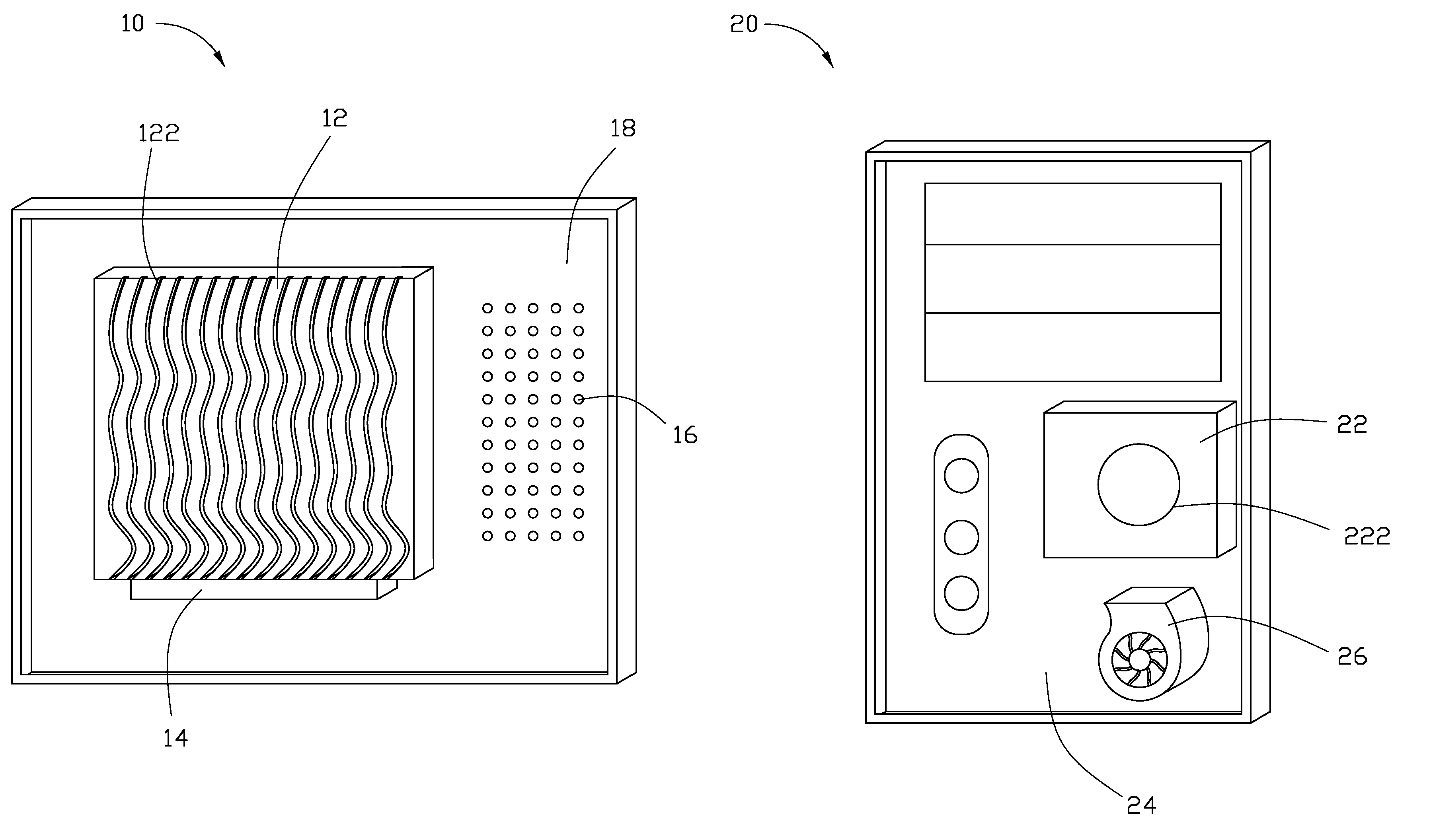
The present disclosure is about a computer enclosure that improves heat dissipation for electronic devices, such as computers. The computer enclosure includes a side plate and a front plate, with the side plate having through holes to dissipate heat. An absorber plate is mounted on the inner wall of the side plate to absorb heat from the electronic elements in the computer enclosure, and a thermoelectric converter is mounted on the inner wall of the side plate in contact with the absorber plate to receive and convert the heat energy into electrical energy. The front plate of the computer enclosure has a cryostat that receives the electrical energy generated by the thermoelectric converter and generates cold air to dissipate heat from the electronic elements. A blower can be added to improve airflow and further enhance heat dissipating efficiency. The patent text is just a brief description of the computer enclosure and its technical effects, and changes can be made to the details of the invention as needed.

Problems solved by technology

However, very often, a heat sink for such a heat-generating component cannot fully satisfy the need for dissipating heat when the heat-generating component works in a highly loaded process or a high frequency mode.

Method used


Image

  • Computer enclosure
  • Computer enclosure
  • Computer enclosure

Examples


Embodiment Construction

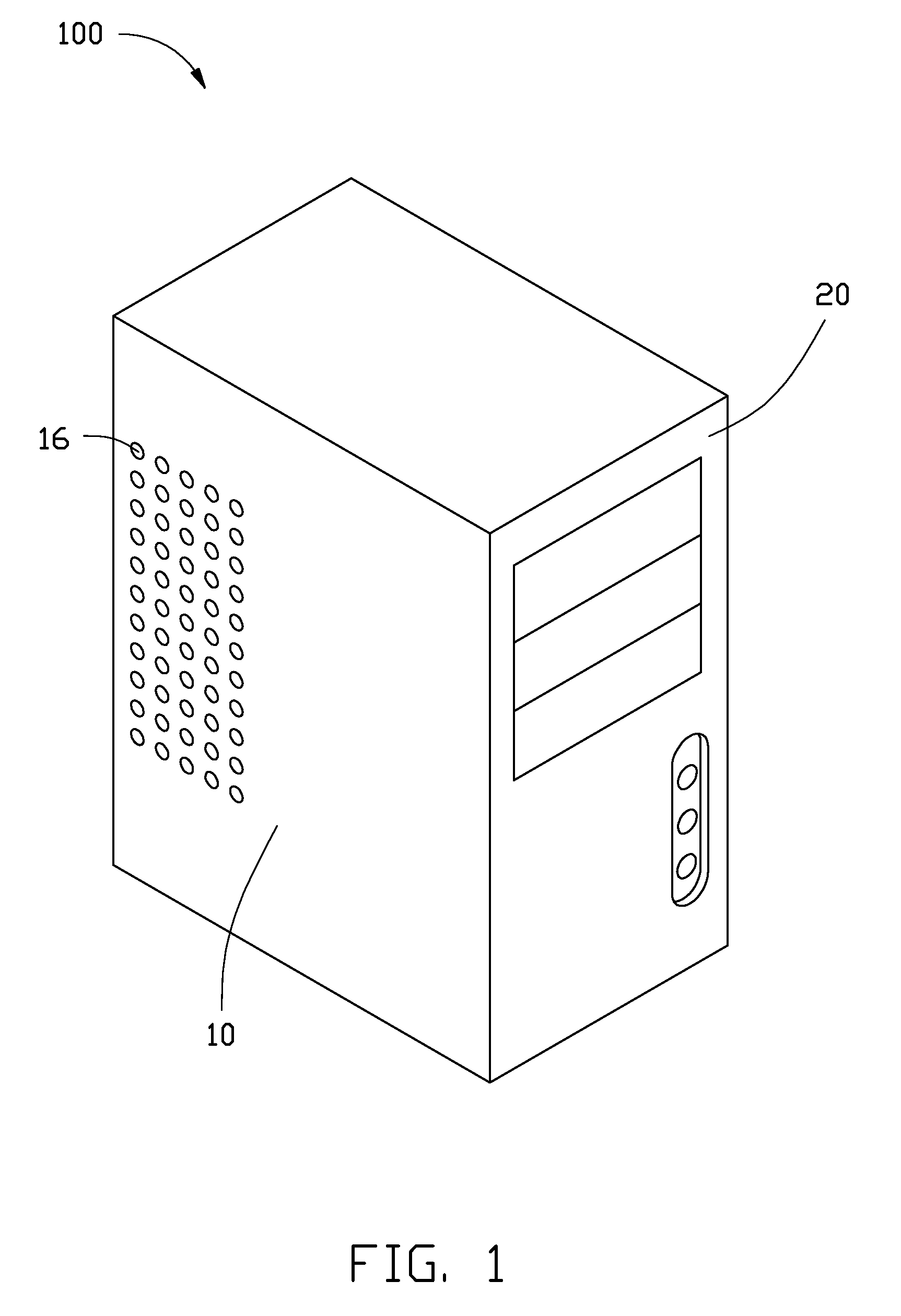
[0009]Referring to FIG. 1 to FIG. 3, an exemplary embodiment of a computer enclosure 100 includes a side plate 10 and a front plate 20, the side plate 10 defining a plurality of through holes 16 to dissipate heat in the computer enclosure 100.

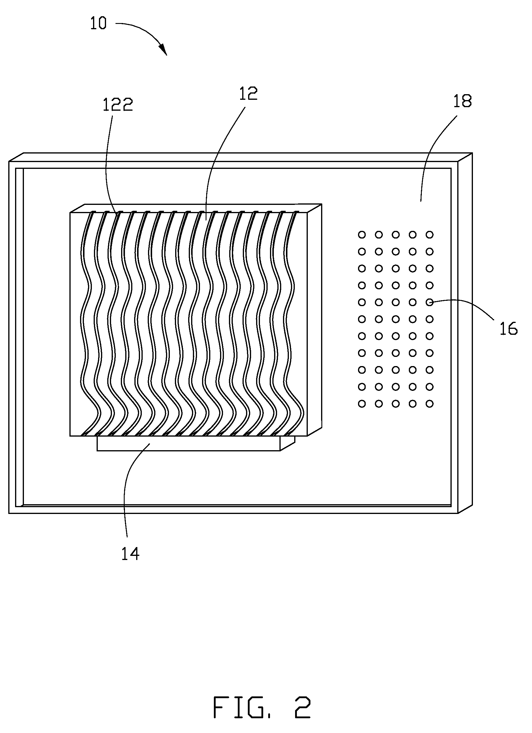
[0010]An absorber plate 12 is mounted to an inner wall 18 of the side plate 10 of the computer enclosure 100, to absorb heat from some electrical elements (such as a central processing unit, not shown) arranged in the computer enclosure 100. A thermoelectric converter 14 is mounted to the inner wall 18 of the side plate 10 of the computer enclosure 100 in contact with the absorber plate 12, to receive heat energy absorbed by the absorber plate 12, and then convert the heat energy to electrical energy. In one embodiment, the absorber plate 12 is rectangular, and a plurality of wavy parallel grooves 122 defined in the absorber plate 12, to improve heat absorbing efficiency.

[0011]A cryostat 22 is mounted to an inner wall 24 of the front plate 20 o...


PUM


Abstract

A computer enclosure includes an absorber plate, a thermoelectric converter, and a refrigerator. The absorber plate is arranged in the computer enclosure to absorb heat generated in the computer enclosure. The thermoelectric converter is arranged in the computer enclosure to receive heat absorbed by the absorber plate, and then convert the absorbed heat to electrical energy. The refrigerator is arranged in the computer enclosure to receive the electrical energy generated by the thermoelectric converter, and then work to generate cold air to dissipating heat in the computer enclosure.

Description

BACKGROUND[0001]1. Technical Field[0002]The present disclosure relates to a computer enclosure.[0003]2. Description of Related Art[0004]In electronic devices, and particularly, computers, heat-generating components, such as central processing units (CPUs), usually generate heat during operation. Generally, a heat sink is mounted on a heat-generating component to dissipate the heat. However, very often, a heat sink for such a heat-generating component cannot fully satisfy the need for dissipating heat when the heat-generating component works in a highly loaded process or a high frequency mode.BRIEF DESCRIPTION OF THE DRAWINGS[0005]FIG. 1 is a schematic, isometric view of an exemplary embodiment of a computer enclosure, the computer enclosure including a side plate and a front plate.[0006]FIG. 2 is a schematic, isometric view of the side plate of the computer enclosure of FIG. 1, but viewed from another perspective.[0007]FIG. 3 is a schematic, isometric view of an exemplary embodiment...

Claims


Application Information

Patent Timeline
Patent Type & Authority Patents(United States)
IPC IPC(8): H05K7/20G05D23/30
CPCG06F1/20
Inventor ZHAN, ZI-YU
Owner HONG FU JIN PRECISION IND (SHENZHEN) CO LTD
Learn More