Foam projectile
a projectile and foam technology, applied in the field of foam projectiles of combat game weapon systems, to achieve the effect of greater distan
- Summary
- Abstract
- Description
- Claims
- Application Information
AI Technical Summary
Benefits of technology
Problems solved by technology
Method used
Image
Examples
first embodiment
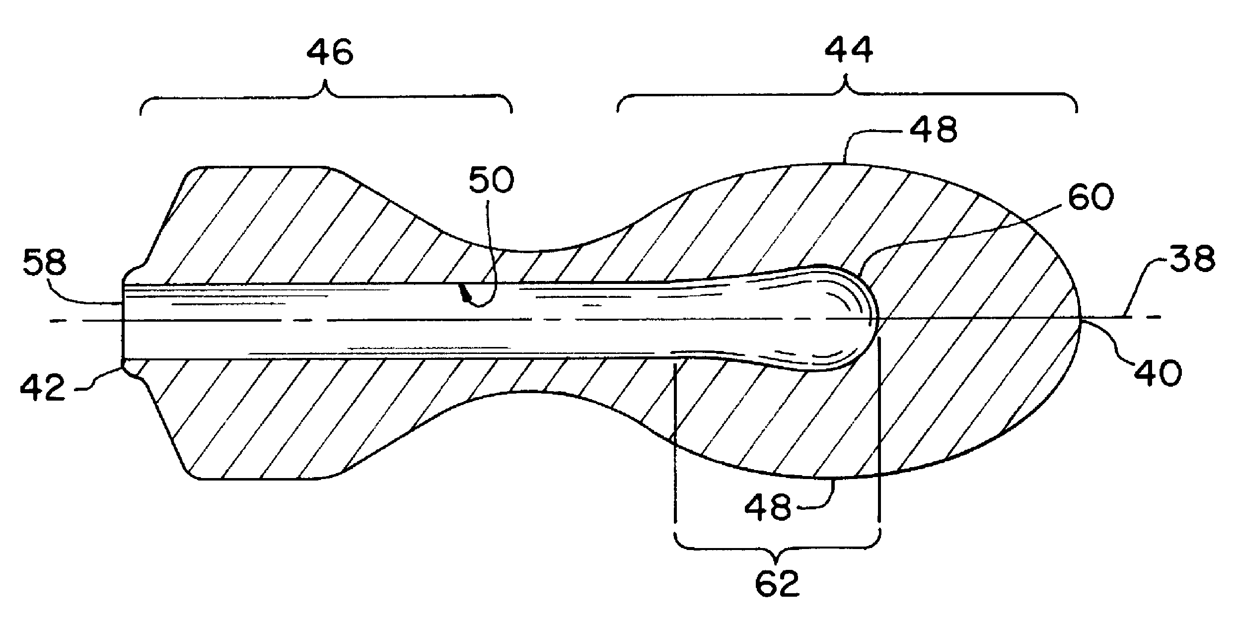
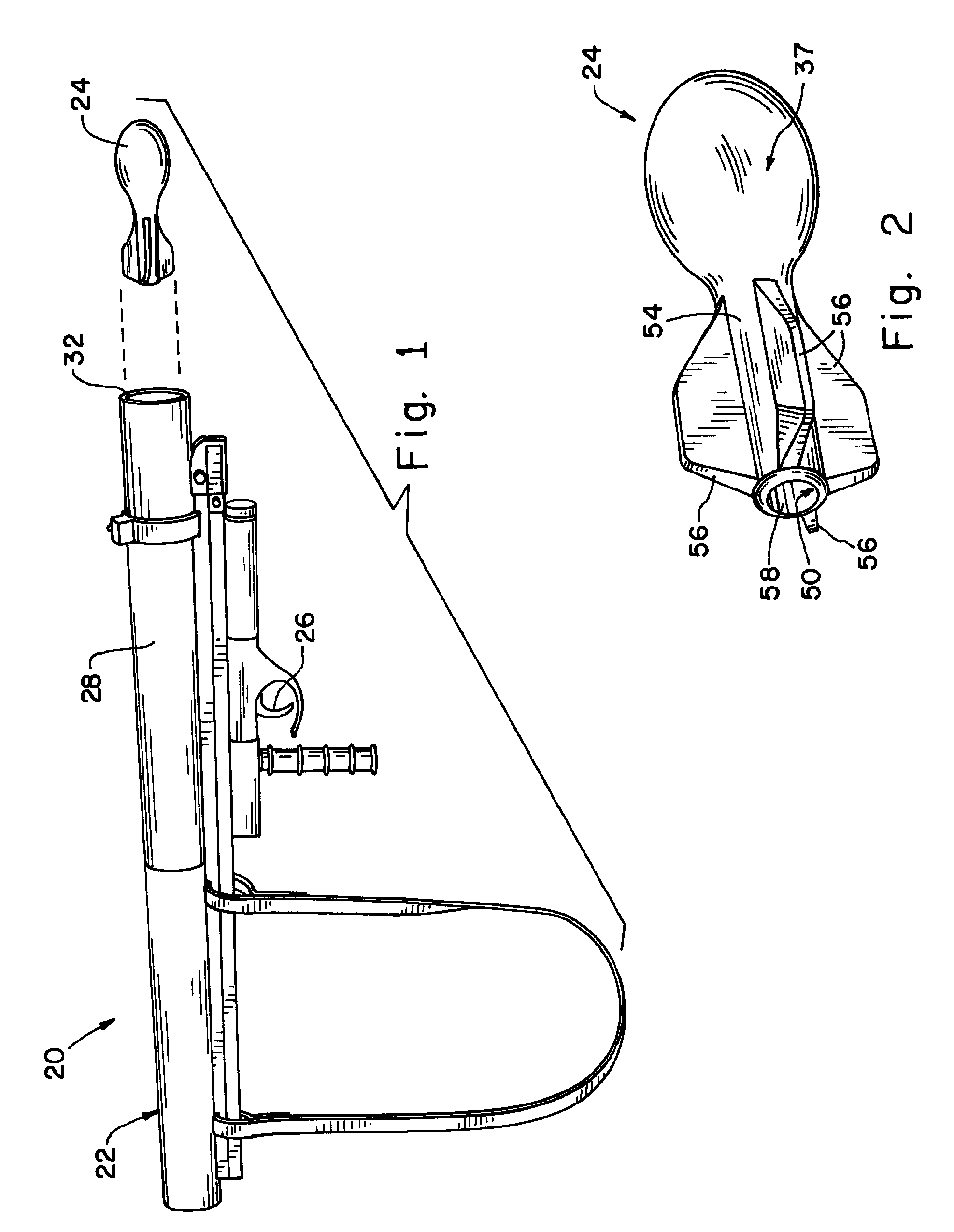
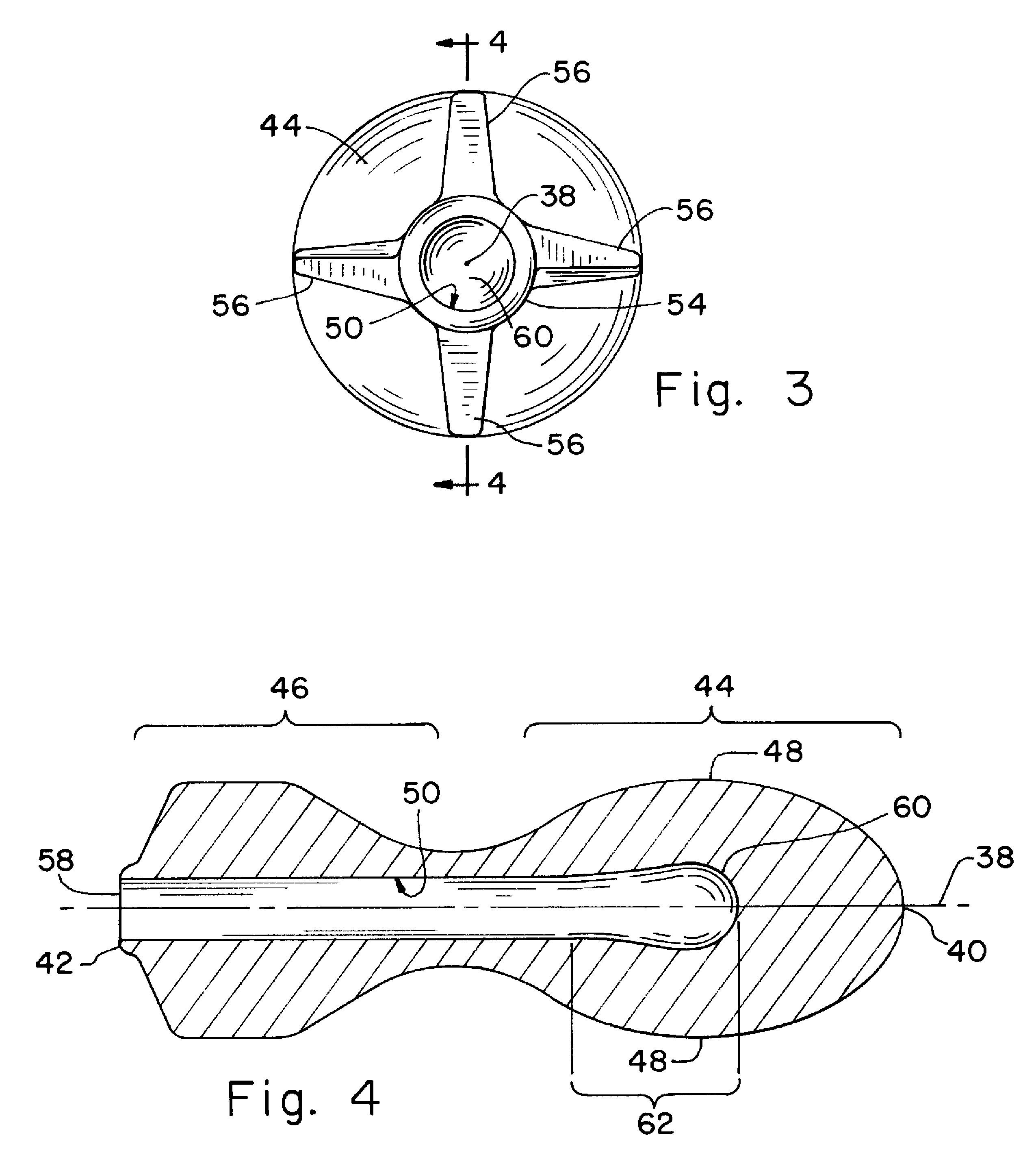
[0032]Referring now to the drawings, and more particularly to FIGS. 1-4, there is shown a combat game weapon system 20 which generally includes a pneumatic launcher 22 and an elastic projectile 24. Projectile 24 is loaded into launcher 22 and expelled therefrom upon squeezing a trigger 26. Combat game weapon system 20 (as well as systems 120, 220, and 320, below) has application to, but is not necessarily limited to, paintball games, although projectile 24 of system 20 may or may not itself carry a paintball to be exploded when projectile 24 strikes a target after having been launched by launcher 22.
[0033]Launcher 22 includes trigger 26 and a barrel 28. Barrel 28 includes a proximal end 30 (a breech end), a distal end 32 (a muzzle end), and a bore 33 having an inside diameter 34. Inside diameter 34 is a structure which is the inside surface of barrel 28 along bore 33 (inside diameter can also correspond to a dimension as well when used in that sense). In an informal sense, launcher ...
third embodiment
[0049]Now, additionally referring to FIGS. 11 and 12, there is shown yet another embodiment of the combat game weapon system of the present invention, that system having the reference number 220. System 220 employs launcher 122 but could employ launcher 22 in place of launcher 122. The foam projectile, now labeled as 124, is shown in bore 33 of barrel 28 of launcher 122. FIG. 11 shows only barrel 28 of launcher 122 and projectile 124. The cross-section line in FIGS. 11 and 12 are taken through the 12 o'clock and 6 o'clock positions of both barrel 28 and projectile 124. Projectile 124 is the projectile according to the present invention. Projectile 124 includes cavity 150. In FIG. 11, projectile 124 has not yet received propellant 36 from launcher 122; stated another way, FIG. 11 shows projectile 124 before firing launcher 122. FIG. 12 shows cavity 150 of projectile 124 having received propellant 36 from launcher 122. FIG. 12 also shows the deformation of the rear end (the trailing e...
fourth embodiment
[0050]Now, additionally referring to FIG. 13, there is shown yet another embodiment of the combat game weapon system of the present invention, that system having the reference number 320. System 320 employs launcher 122 but could employ launcher 22 in place of launcher 122. The foam projectile, now labeled as 224, is positioned partially inside of barrel 28 of launcher 122. FIG. 13 shows only barrel 28 of launcher 122 and projectile 224. The cross-section line in FIG. 13 is taken through the 12 o'clock and 6 o'clock positions of both barrel 28 and projectile 224. Projectile 224 is the projectile according to the present invention and is in the form of a rocket propelled grenade. Projectile 224 includes cavity 250. Projectile 224 has the cross-section of a rocket propelled grenade (“RPG”), with a rear portion (the trailing portion) that works under the principle of operation as discussed above. FIG. 13 shows cavity 250 receiving propellant 36 from launcher 122. Double-arrow 272 shows...
PUM
 Abstract
Description
Claims
Application Information
 - R&D Engineer
- R&D Manager
- IP Professional
- Industry Leading Data Capabilities
- Powerful AI technology
- Patent DNA Extraction
Browse by: Latest US Patents, China's latest patents, Technical Efficacy Thesaurus, Application Domain, Technology Topic, Popular Technical Reports.
© 2024 PatSnap. All rights reserved.Legal|Privacy policy|Modern Slavery Act Transparency Statement|Sitemap|About US| Contact US: help@patsnap.com


