
Heat-shrinkable cylindrical label

a cylindrical label and shrinkable technology, applied in the direction of thermal insulation containers, closure caps, bottling operations, etc., can solve the problems of not easy to conduct the heat of the container or the like to the user, short winding length, and inability to obtain sufficient adhesive strength at ease, so as to prevent the effect of sure generation

Inactive Publication Date: 2010-12-14
FUJI SEAL INTERNATIONAL INC
View PDF14 Cites 2 Cited by
  • Summary
  • Abstract
  • Description
  • Claims
  • Application Information

AI Technical Summary

Benefits of technology

The present invention provides a heat-shrinkable cylindrical label that has a center seal section and does not become thick or hard. The center seal section can be formed by overlapping the label substrate's inner layer sheet with the rear face of the outer layer sheet and sticking them together with a solvent or adhesive. The label substrate has one side edge inside the other side end section, creating a gentle line or curved line in the label's external form. The label is attached to a product by shrinkage, and the center seal section does not swell or protrude from the label's edge. The label has a beautiful circumferential face shape and is easy to apply.

Problems solved by technology

Accordingly, even if a container or the like to which this cylindrical label is attached is heated or cooled, the heat of the container or the like is not easily conducted to the user.
As a result, when the cylindrical label continuum wherein the cylindrical label is continuously extended is wound into a roll form, there is caused a problem that the length of the winding becomes short.
The structure shown in FIG. 20(a) also has a problem that: the adhesive 105 is coated onto the foamed resin sheet 102; thus, if the amount of the adhesive is small, a sufficient adhesive strength is not obtained at ease.
For this reason, the external appearance of the product to which the label is attached is bad.
Thus, the adjustment is complicated.
For example, similar problems are caused in the case of using a label substrate wherein a nonwoven cloth, Japanese paper or the like is laminated.
Furthermore, when the material of a heat-shrinkable sheet is different from that of a foamed resin sheet or nonwoven cloth, the two may be unable to be stuck to each other with a solvent.

Method used


Image

  • Heat-shrinkable cylindrical label
  • Heat-shrinkable cylindrical label
  • Heat-shrinkable cylindrical label

Examples


first embodiment

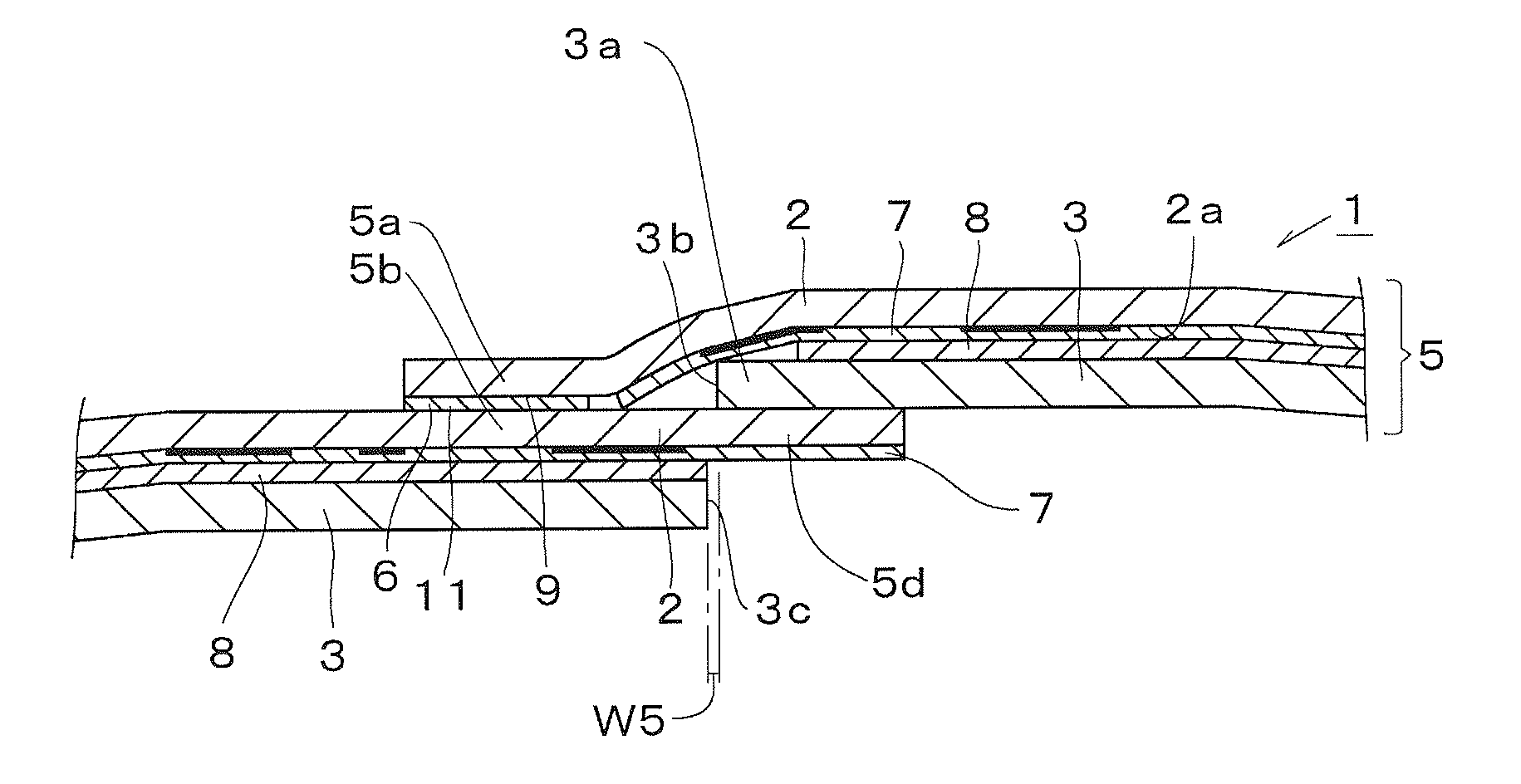
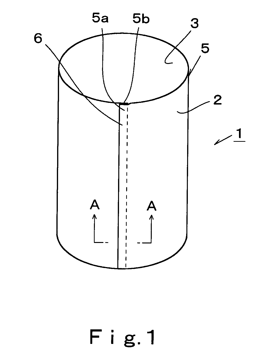
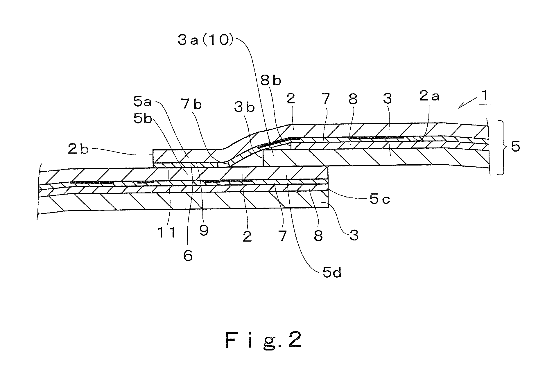
[0056]In FIGS. 1 to 3, reference number 1 represents a heat-shrinkable cylindrical label formed by overlapping both side end sections 5a and 5b of a label substrate 5 wherein an inner layer sheet 3 is laminated over a rear face 2a of an outer layer sheet 2 having heat-shrinkability with each other so as to make the label substrate into a cylindrical form, and then sticking the overlapped portions to each other with a solvent or adhesive, thereby forming a center seal section 6.

[0057]This label substrate 5 has a structure wherein at least the outer layer sheet 2, a design printed layer 7, an adhesive layer 8 and the inner layer sheet 3 are successively laminated, these layers being arranged from the front face side of the label substrate 5 in the order that the layers are described.

[0058]Specifically, the label substrate 5 is formed into a rectangular form having a given width and length. As also illustrated in FIG. 3, the label substrate 5 is made of a laminate wherein the design pr...

second embodiment

[0091]A second embodiment relates to a cylindrical label wherein an adhesive layer 8 is formed up to one side edge 3b of an inner layer sheet 3. Its portions different from the first embodiment will mainly be described hereinafter, and about the same or similar constituents, the corresponding terms and reference numbers are incorporated into the specification and the drawings by reference. Thus, description thereof may be omitted.

[0092]As illustrated in FIGS. 5 and 6, the present embodiment is a heat-shrinkable cylindrical label 1 wherein both side end sections 5a and 5b of a label substrate 5 wherein an inner layer sheet 3 is laminated onto the rear face 2a of a heat-shrinkable outer layer sheet 2 through an adhesive layer 8 are overlapped with each other to make the label substrate 5 into a cylindrical form thereby forming a center seal section 6, and wherein: one side edge 8b of the adhesive layer 8 is formed at least up to one side edge 3b of the inner layer sheet 3; the layer t...

third embodiment

[0103]A third embodiment relates to a cylindrical label wherein inner layer sheet 3 portions in one side end section 5a and the other side end section 5b of a label substrate 5 do not overlap with each other in the vertical direction. Its portions different from the first and second embodiments will mainly be described hereinafter, and about the same or similar constituents, the corresponding terms and reference numbers are incorporated into the specification and the drawings by reference. Thus, description thereof may be omitted.

[0104]As illustrated in FIG. 8(a), in an overlap margin section 5d of a label substrate 5 which extends outward from a center seal section 6, an inner layer sheet 3 in this overlap margin section 5d is formed to be positioned outside one side edge 3b of the inner layer sheet 3 in the one side end section 5a of the label substrate 5 with which the other side edge 3c of the inner layer sheet 3 is overlapped. In other words, in the overlap margin section 5d ge...


PUM

PropertyMeasurementUnit
width W1aaaaaaaaaa
width W2aaaaaaaaaa
lengthaaaaaaaaaa

Abstract

The heat-shrinkable cylindrical label of the invention comprises a laminated substrate made of two or more layers which have an outer layer sheet and an inner layer sheet. In one side end section of this label substrate, an outer layer sheet exposure section having no inner layer sheet is formed. This outer layer sheet exposure section is overlapped with the other end section of the front face of the label substrate to form a center seal section. In such a heat-shrinkable cylindrical label, the center seal section can be formed without interposing the inner layer sheet. Accordingly, the center seal section does not become thick. Thus, a heat-shrinkable cylindrical label having a beautiful external appearance can be provided.

Description

BACKGROUND OF THE INVENTION[0001]1. Field of the Invention[0002]The present invention relates to a heat-shrinkable cylindrical label which is attached to a container or the like by heat shrinkage, and a method of producing a longitudinal cylindrical label continuum wherein the cylindrical label is continuously extend sectioned.[0003]2. Background Art[0004]Heat-shrinkable cylindrical labels (shrinkable labels each formed into a cylindrical form) are used in the state that they are attached to containers such as drink bottles or cosmetic containers.[0005]Such a heat-shrinkable cylindrical label is made of a label substrate which has a sheet (generally called a film in some cases) made of a synthetic resin and having heat shrinkability. Both side end sections of this label substrate are overlapped with each other, and the overlapped portions are stuck onto each other, thereby forming a center seal section.[0006]As this label substrate, there are used substrates of various kinds, exampl...

Claims


Application Information

Patent Timeline
Patent Type & Authority Patents(United States)
IPC IPC(8): B41M5/00G03G7/00B44C1/17B31D1/02B32B7/04B65D25/34B65D81/38G09F3/00G09F3/04
CPCB31D1/021B32B5/022B32B5/18B32B7/04B32B27/065B32B27/10B32B27/12B32B27/302B32B27/36B32B29/00G09F3/04B31D1/027Y10T428/24868B32B2255/02B32B2255/102B32B2255/26B32B2307/304B32B2307/4023B32B2307/412B32B2307/736B32B2307/738B32B2307/75B32B2405/00B32B2519/00Y10T428/24851Y10T428/24802Y10T428/24843Y10T428/24934
Inventor SUZUKI, MASAHITOSAKAMOTO, TOORUHASHIMOTO, TAKEHISAOSE, YASUOKAMINAGA, MASAHIROHOZUMI, NAOMI
Owner FUJI SEAL INTERNATIONAL INC
Learn More